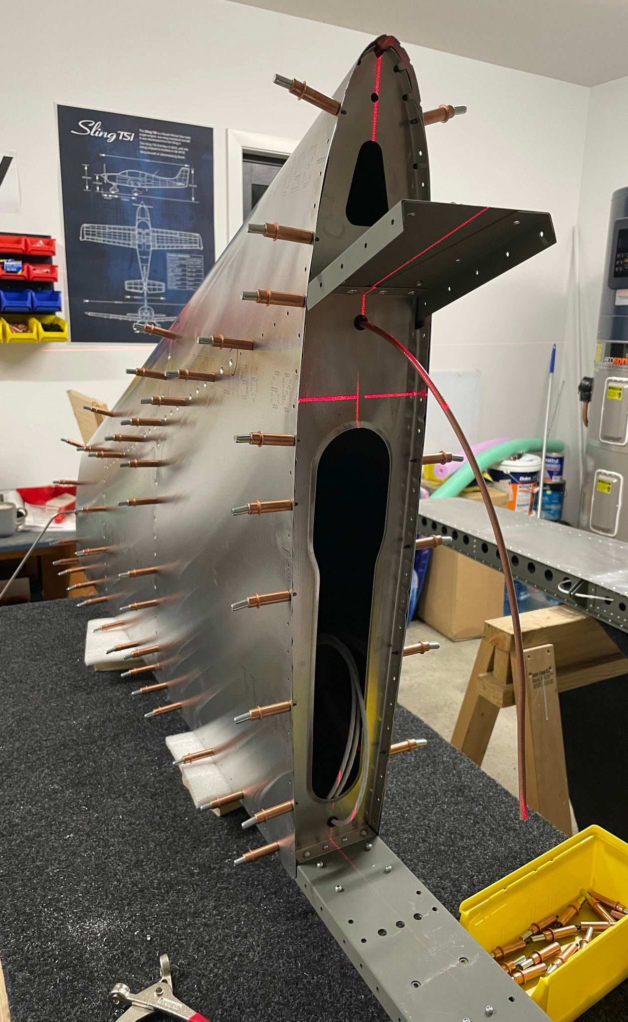
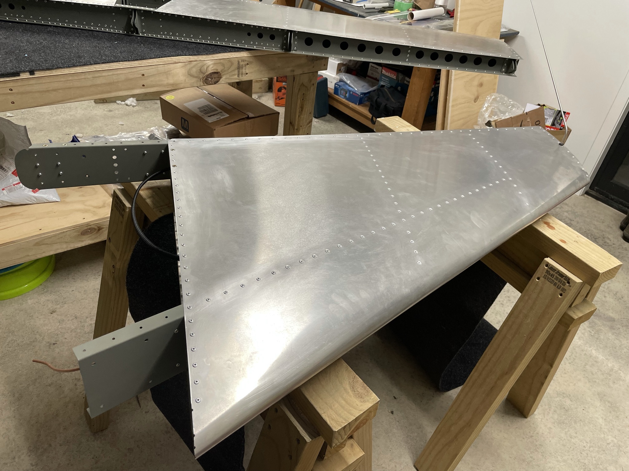
Vertical Stabiliser Completion
Another big piece of plane done.
Drilling out rivets
There are two rivets in the rear spar adjacent rivnuts which I wasn't quite happy with, which I had put in before getting my very handy angled rivet puller from ATS which weren't sitting flush with the spar. I punched out the mandrel on both and drilled out the heads with a 4mm drill bit, but unfortunately elongated the holes slightly.
Luckily I was able to ream them out to 4.9mm and insert 4.8mm rivets without too much fuss, but definitely a reminder to double check the heads of the rivets are flush before pulling them!
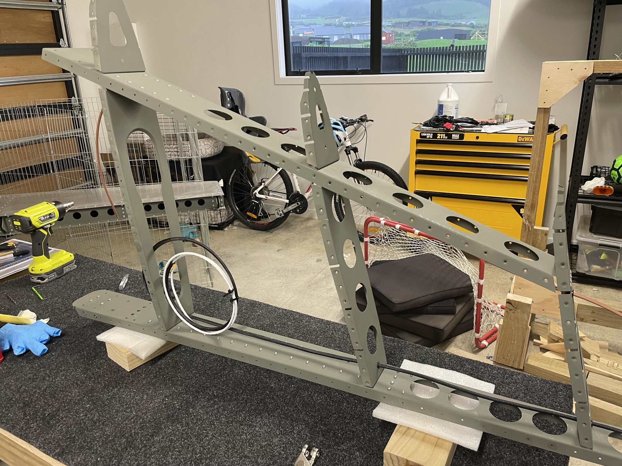
With that done the skin can be test-fitted for match-drilling.
Skin test fit and match-drilling
Again the laborious job of drilling out all the dimpled holes to 3.3mm to accept the 3.2mm rivets. Thankfully this skin only uses one rivet size so no swapping drill bits and nosepieces back and forth. The undimpled holes lined up pretty well after clecoing so much less final drilling of the other holes needed.
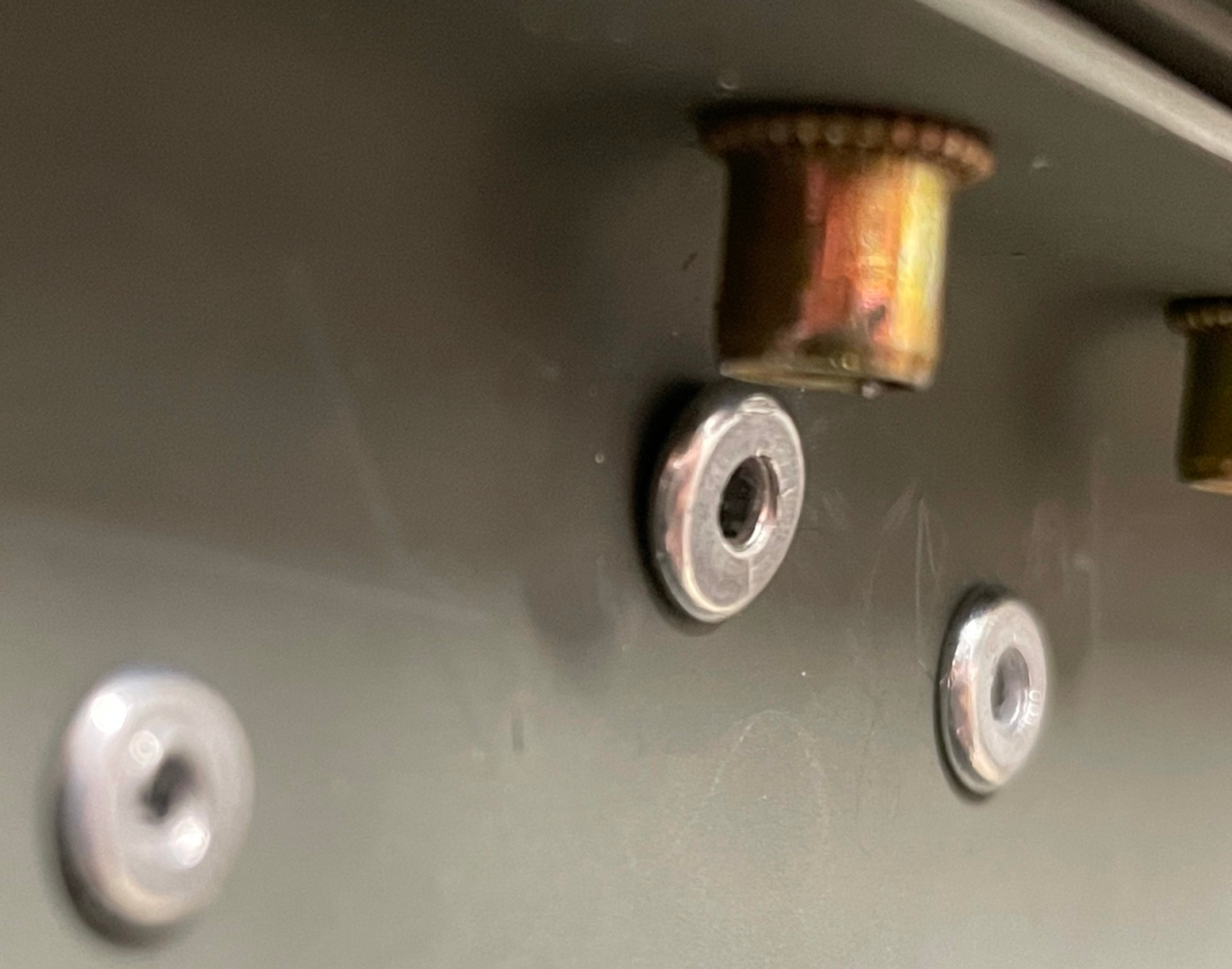
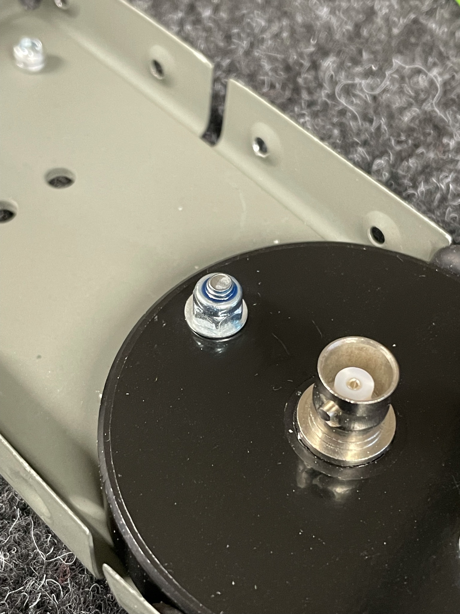
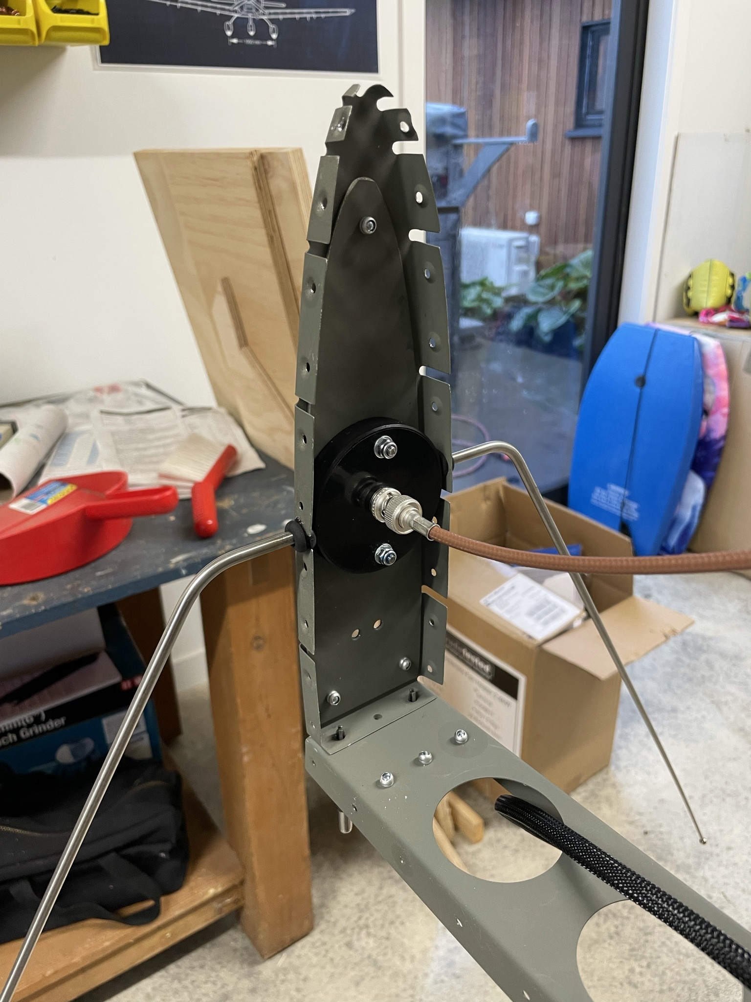
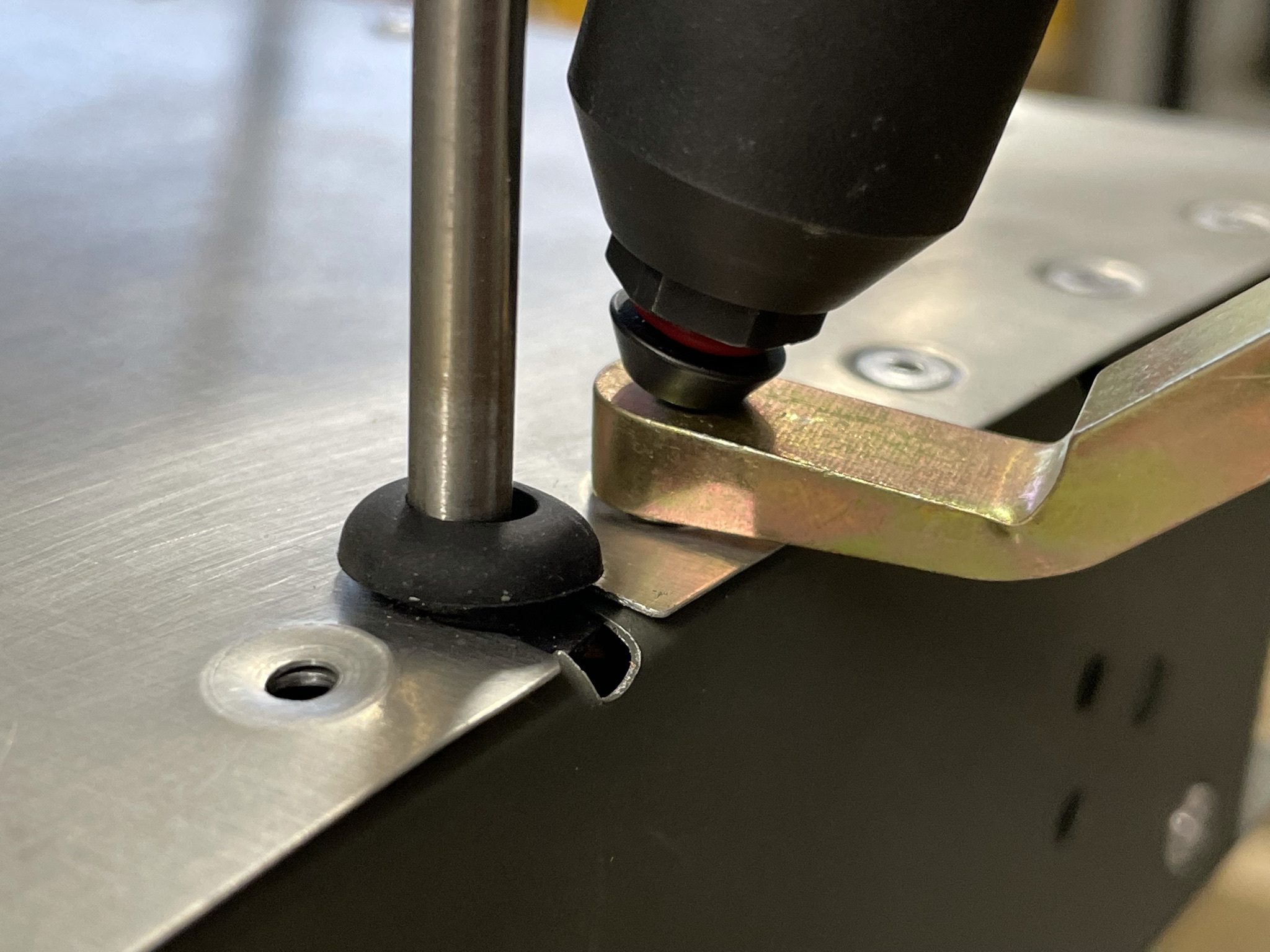
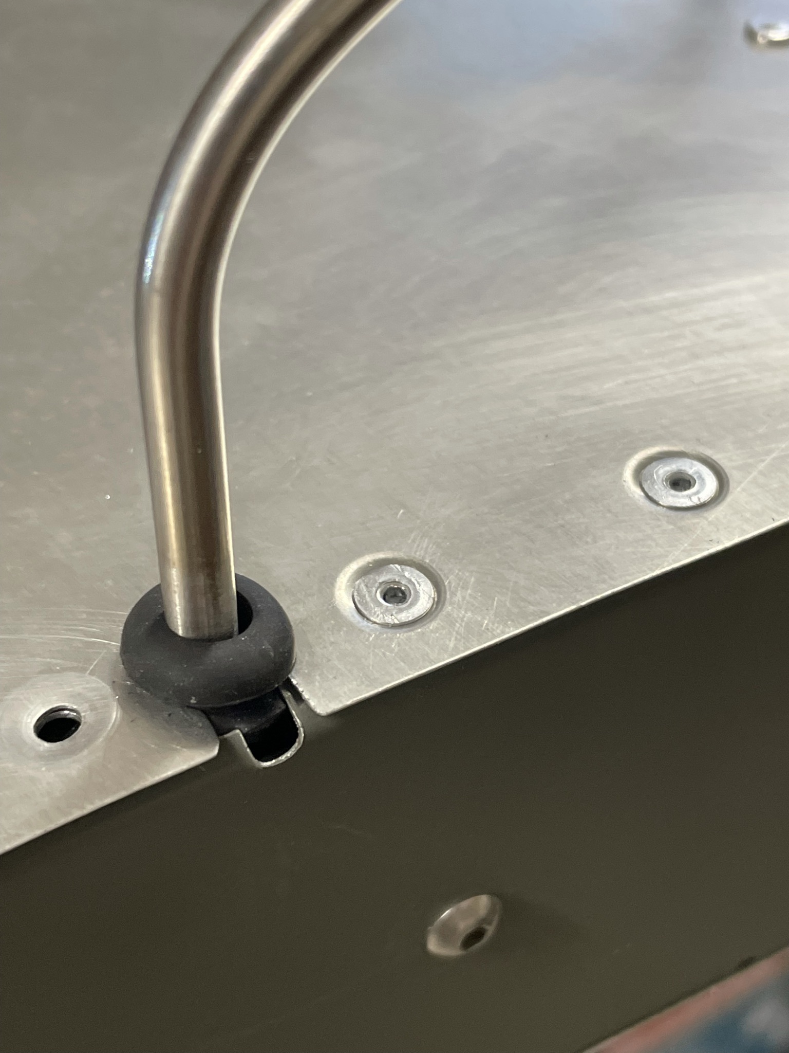
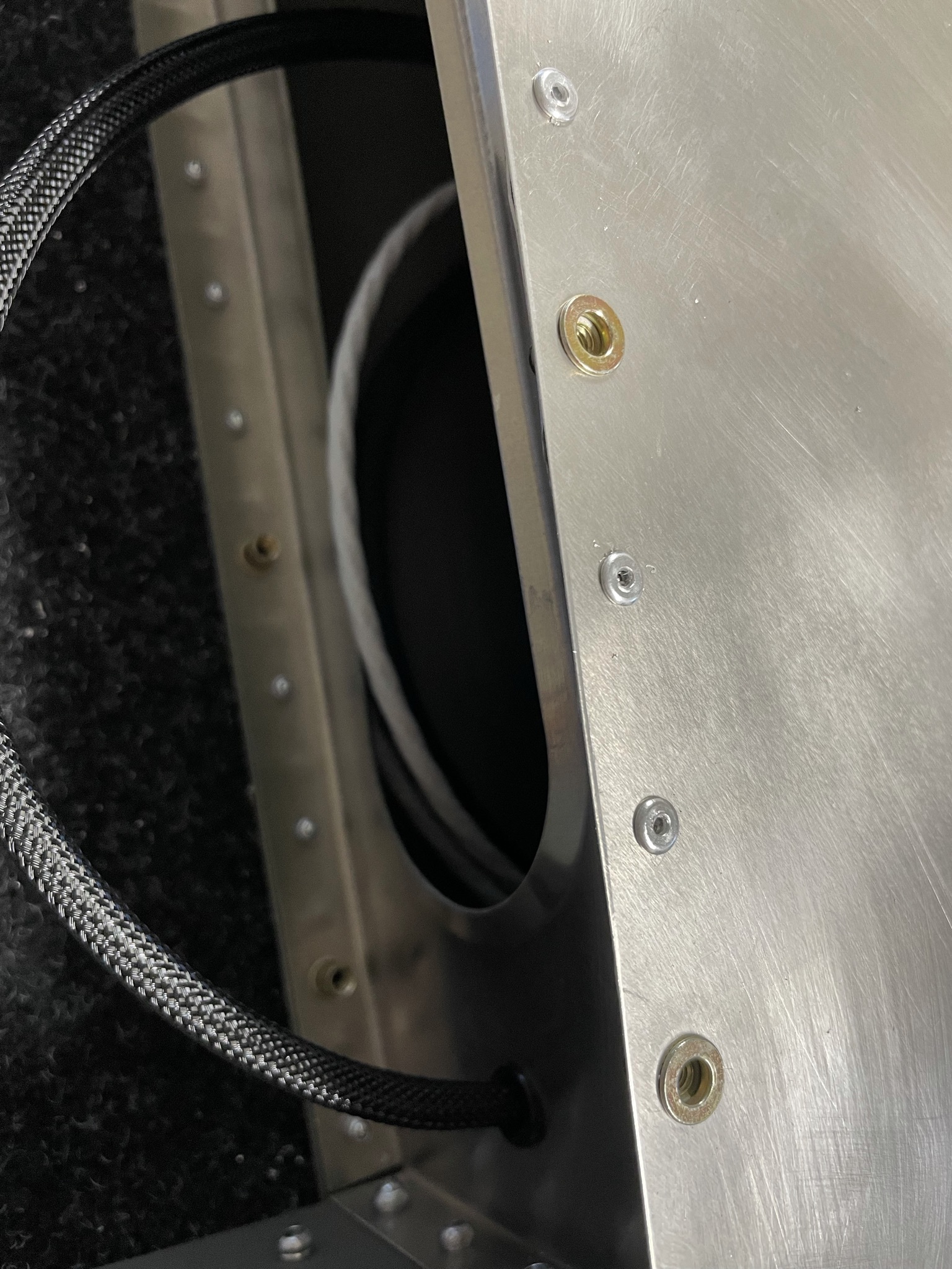
VOR antenna placement
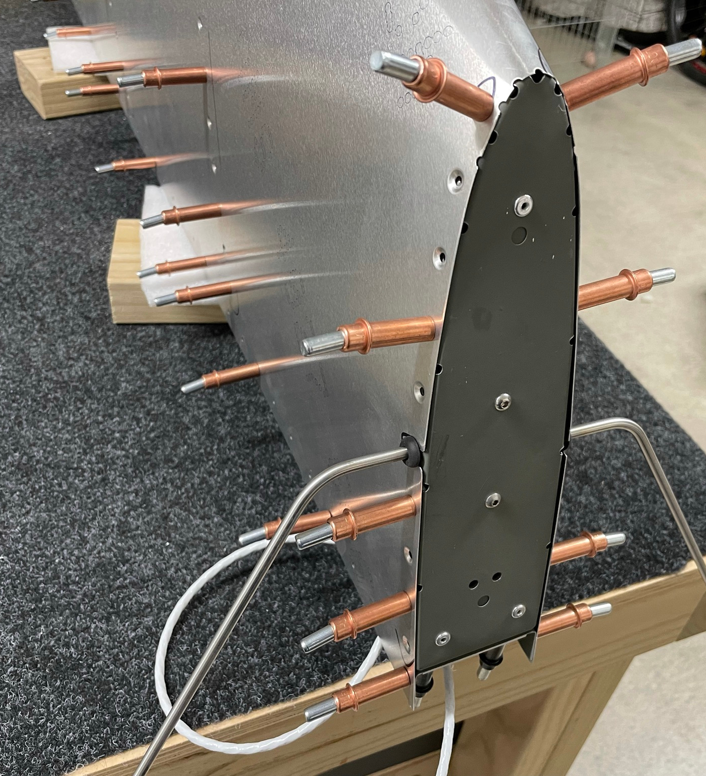
The VOR antenna was a bit tricky to fit in, but I found the best way was to install the antenna including grommets into the top rib, and then slide the skin in from the bottom before dimpling. This seems to capture the grommets the best.
Final assembly
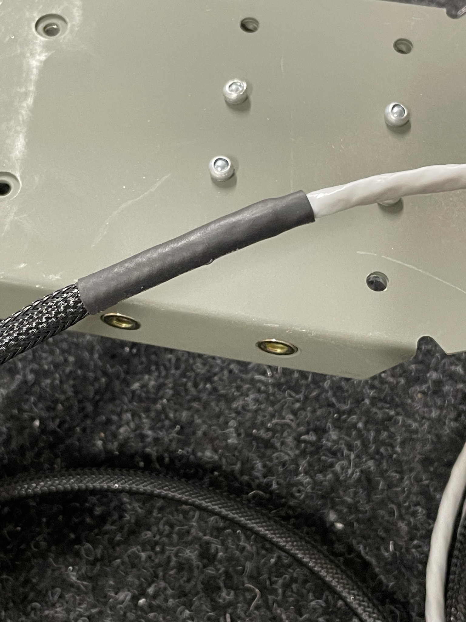
I ordered some heatshrink and flexible sleeving for the electrical cabling so fitted that to the beacon wiring after removing the skin for priming.
Although not in the manual, a number of builders have suggested putting Loctite on the VOR antenna screws and locknuts. I've used Loctite 243 for this.
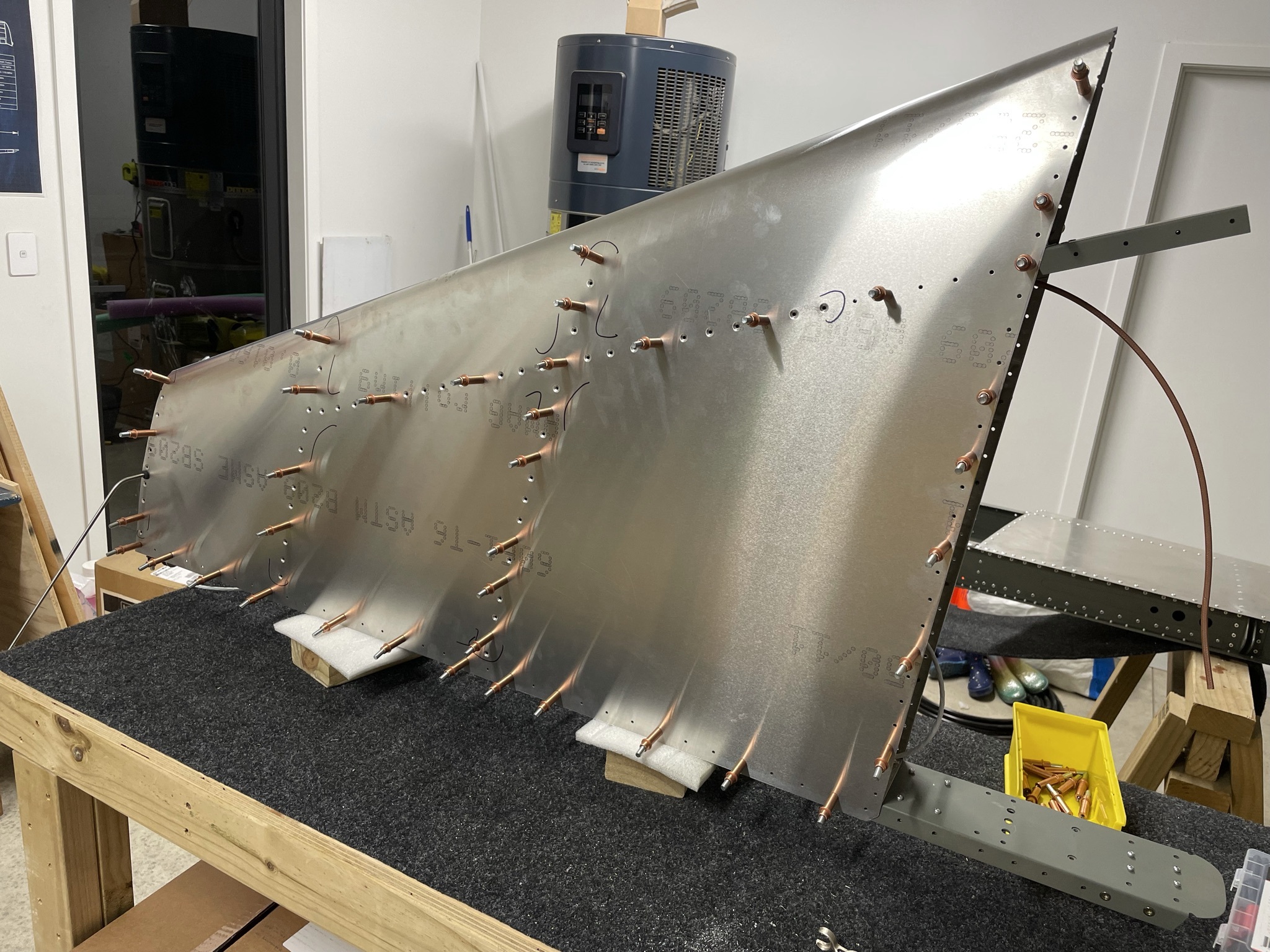
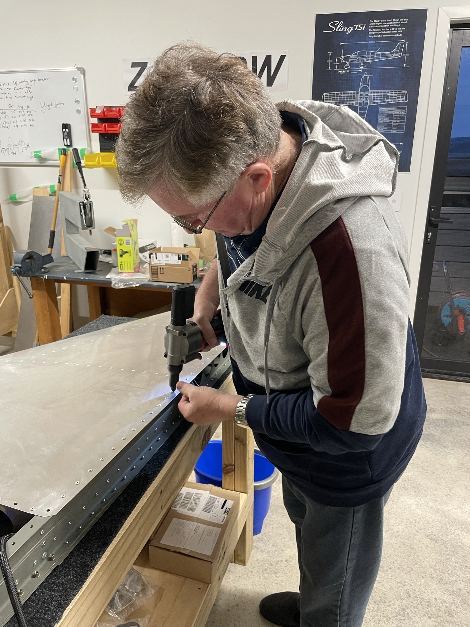
With all the prep done, all that's left is to rivet!
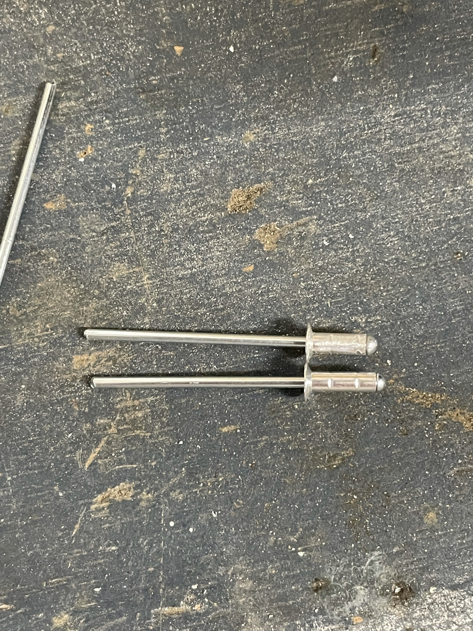
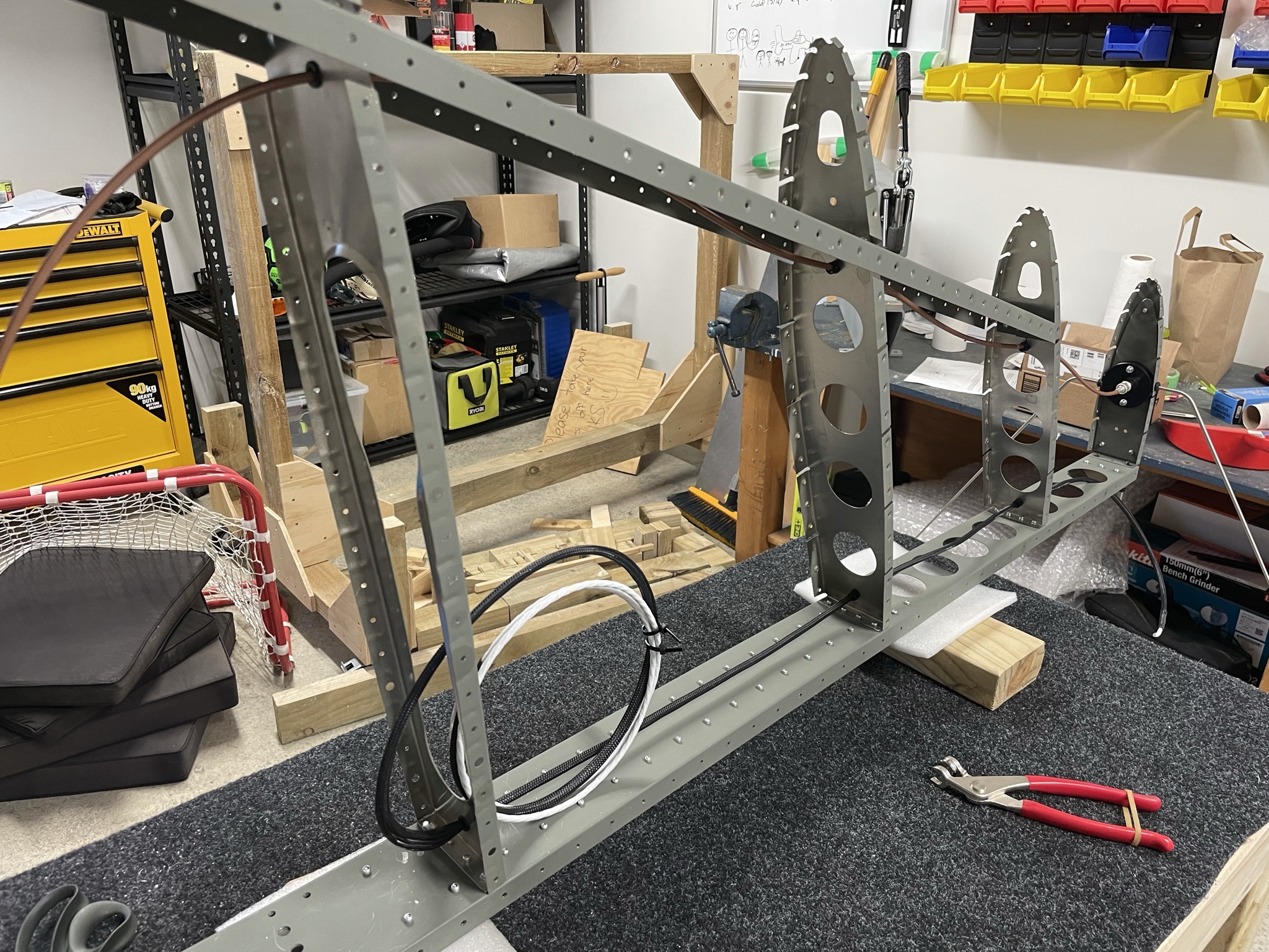
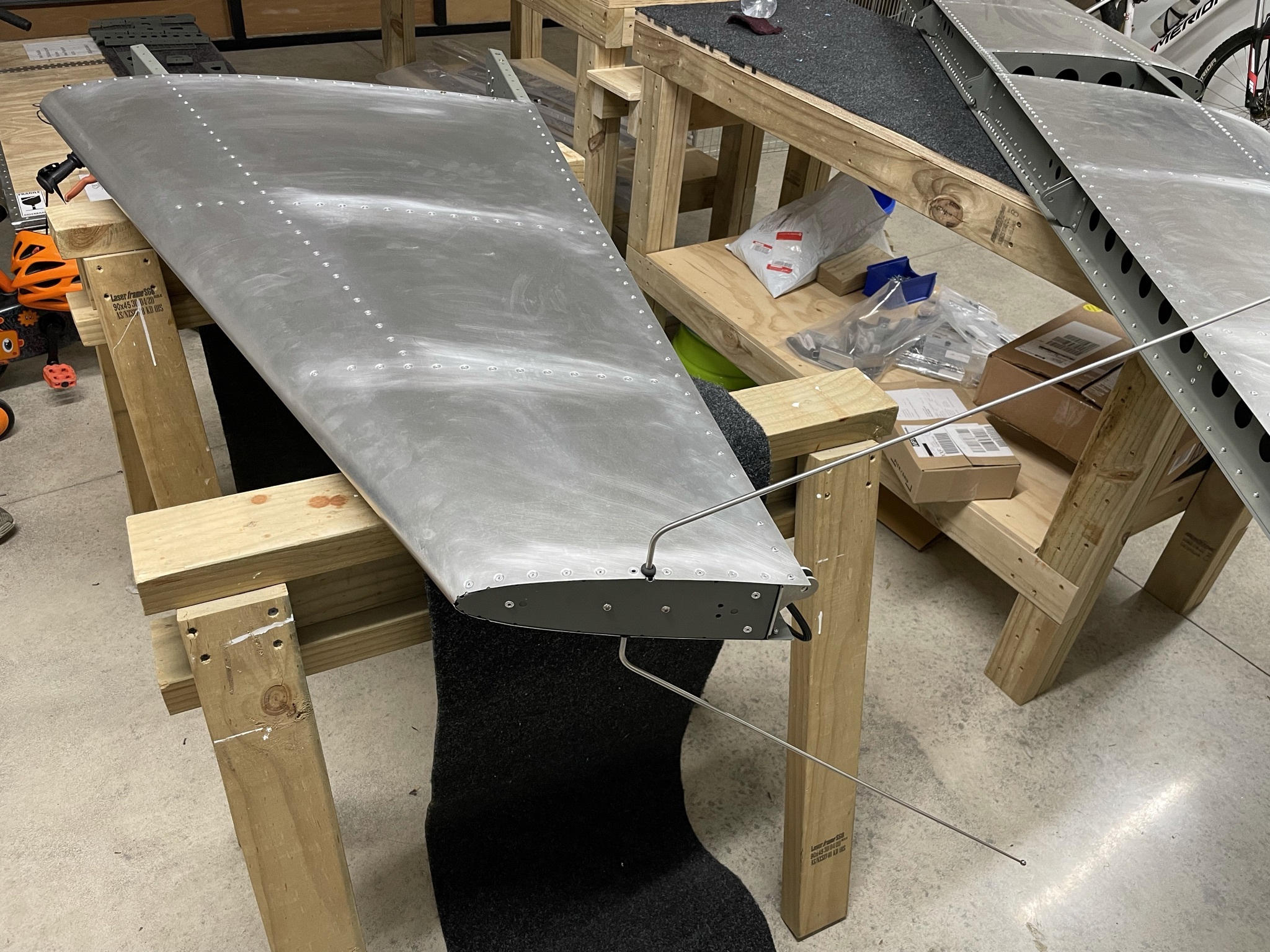
I neede to shorten one rivet to fit against VOR antenna. I used my bench grinder which flared the end a little, so the rivet required a bit of sanding down to nominal diameter to fit the 3.3mm dimpled hole."
Short rivet went in flush with the angle puller. The head is a little marred from using my bench vise while reinserting the mandrel. I really need to make a holder to use the DRDT-2 to do this job as Evan suggests.
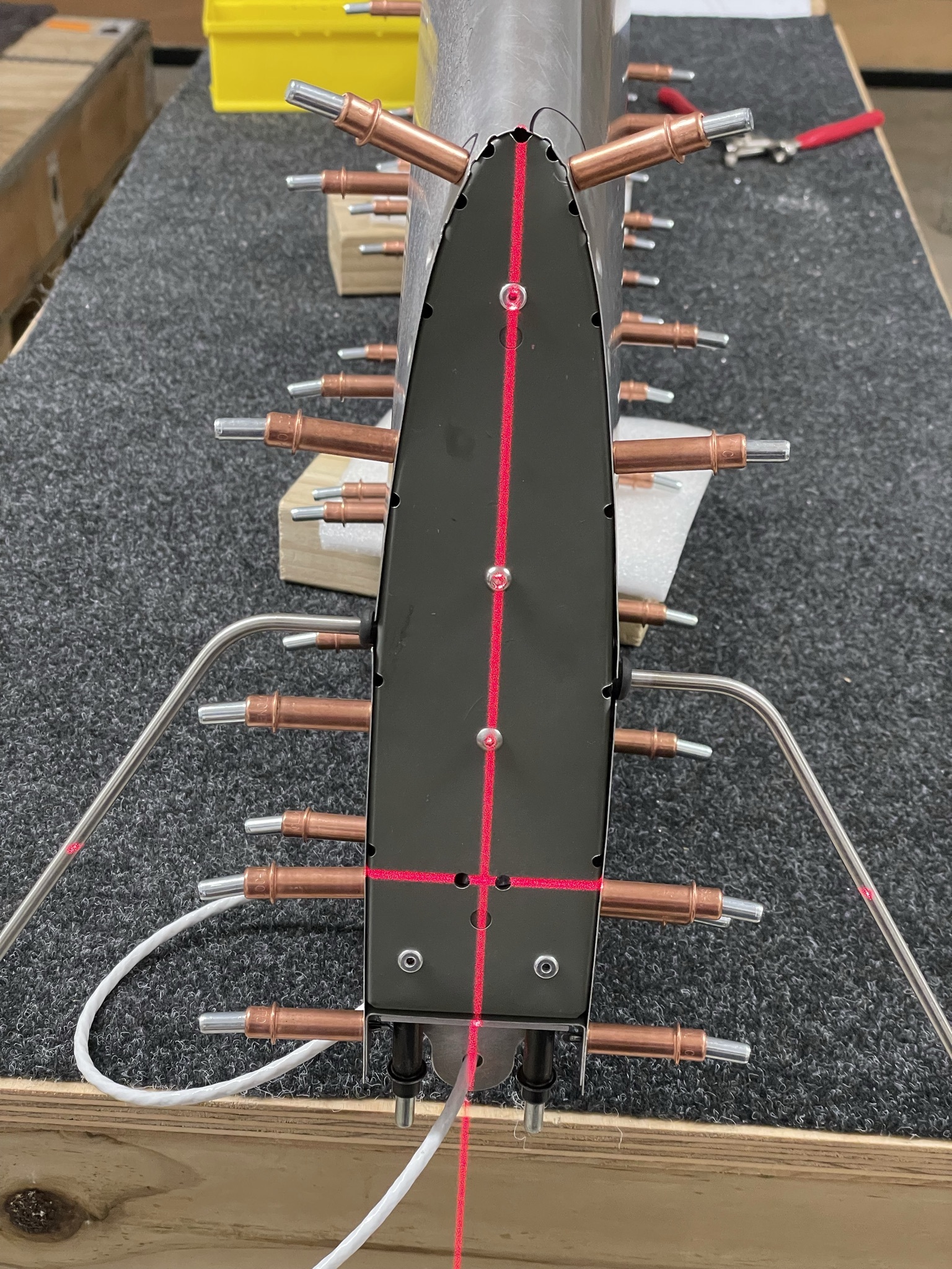
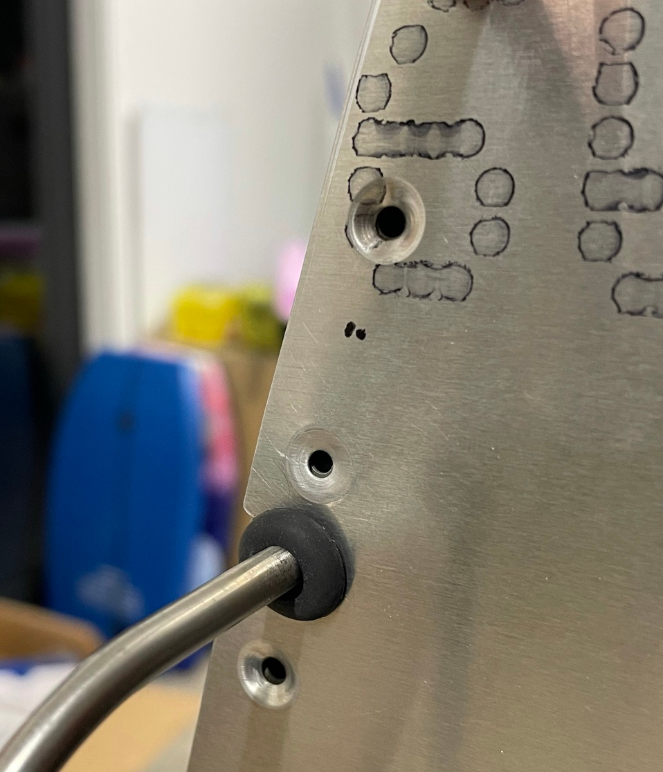
I managed to get away with only one rivet on this side needing to be shortened to account for interference with the VOR antenna, but the rivet adjacent to the semicircular notch in the rib is over the widest part of the antenna base and does not even leave enough room for the base of the mandrel, let alone any rivet material.
I'm unsure what to do finally with this, but its not exactly structural once the rest of the rivets are in, so I'm 90% sure it will just get epoxy filler and paint eventually. I've flattened it by reversing the dimple die and squashing it out in the meantime.
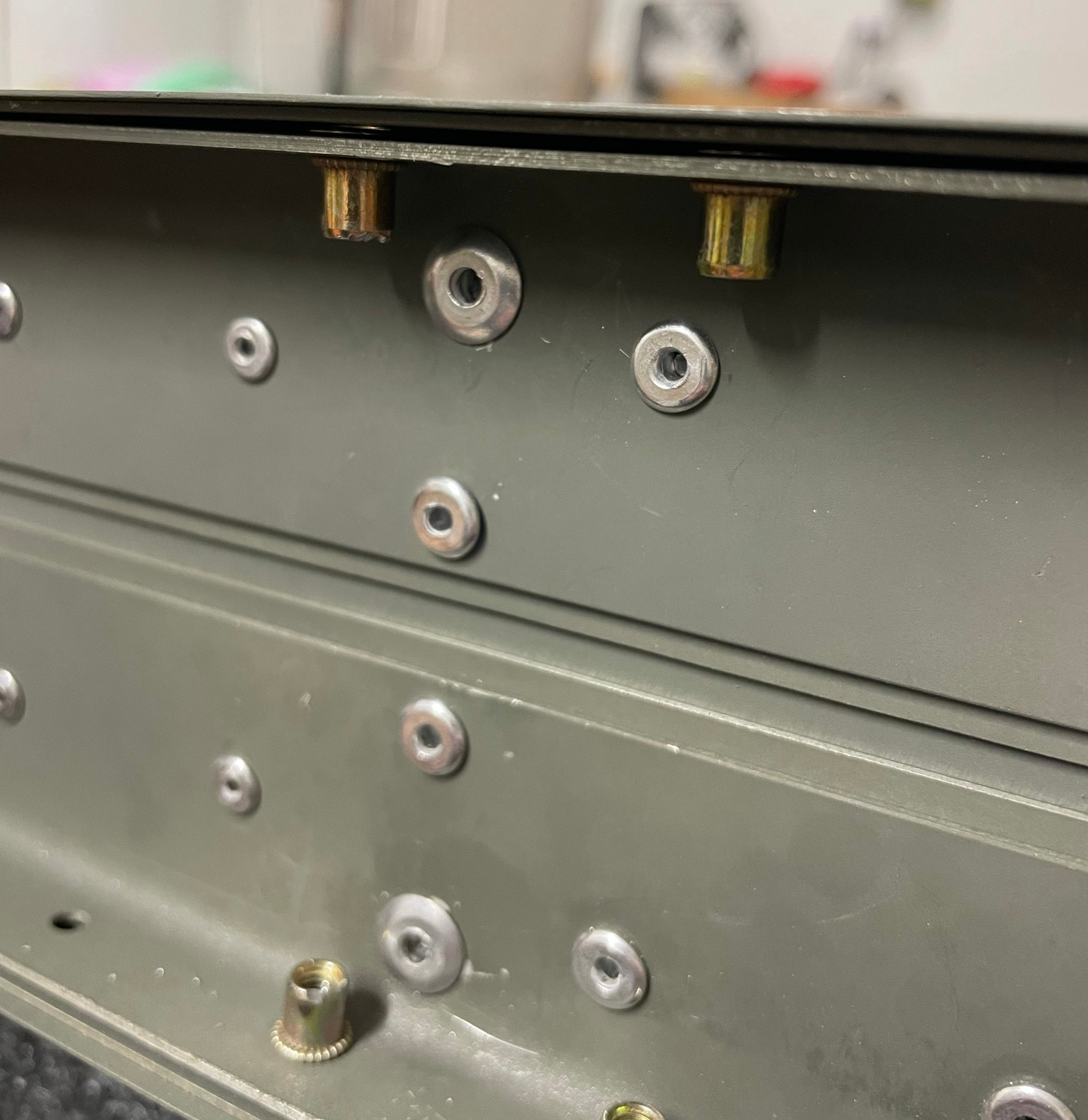
Final step is to install two M4 rivnuts each side.
Complete!
Now onto the rudder...