Vertical Stabiliser Prep and Assembly
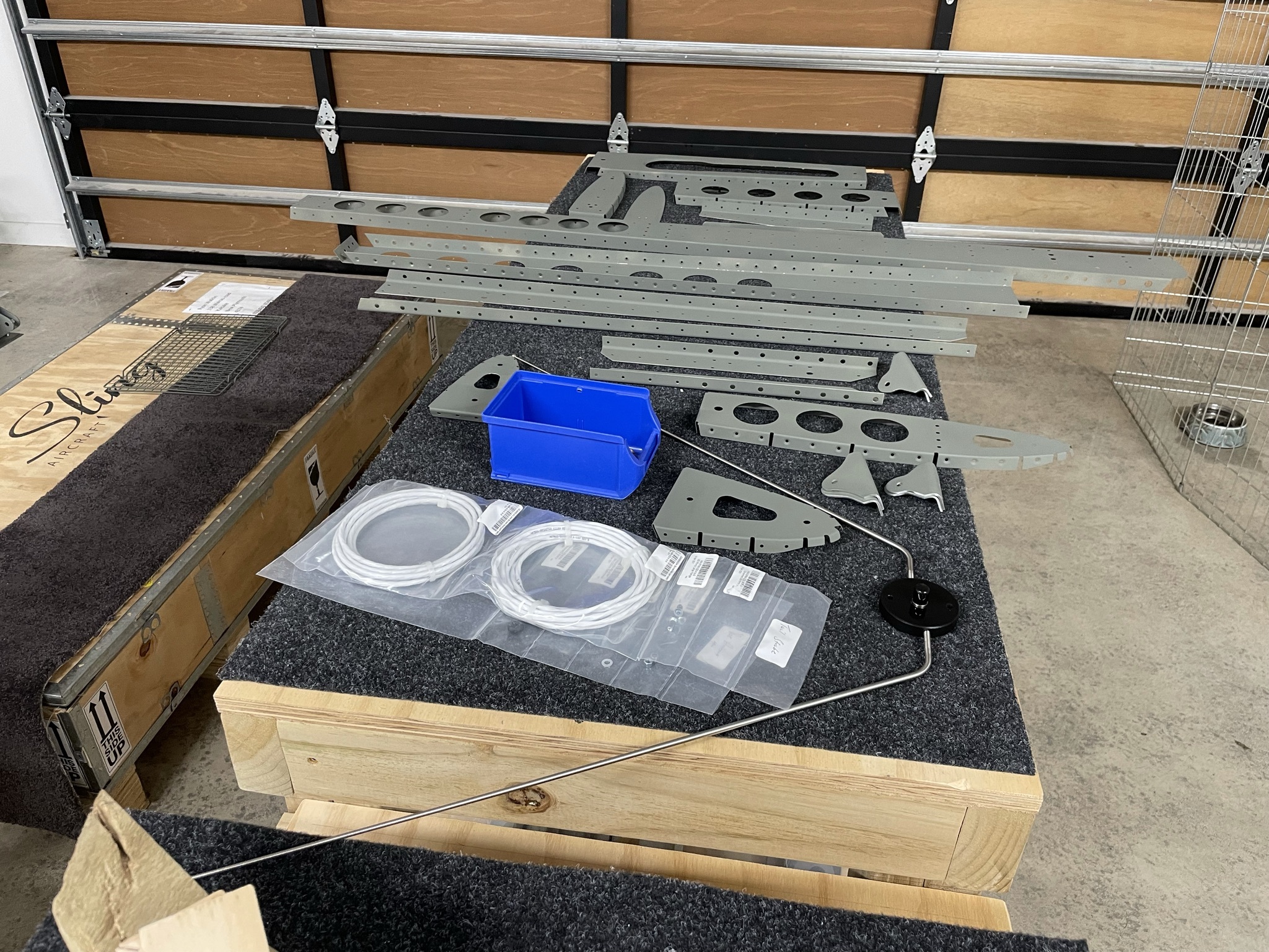
Parts Prep
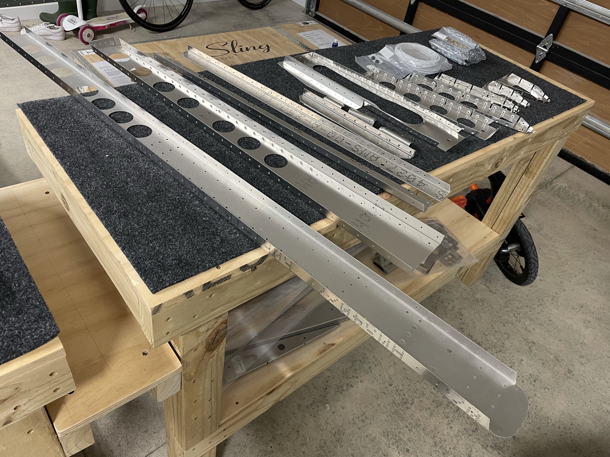
The vertical stabiliser is a smaller part than the HS, but has some added complexities, namely the use of rivnuts, and (in my case at least) the need to install a VOR antenna.
I'm also planning on a static wick on the rudder, which will mean a bonding strap between the rudder and VS, so I'm figuring out the best place to put a nut plate on the rear VS spar to facilitate this.
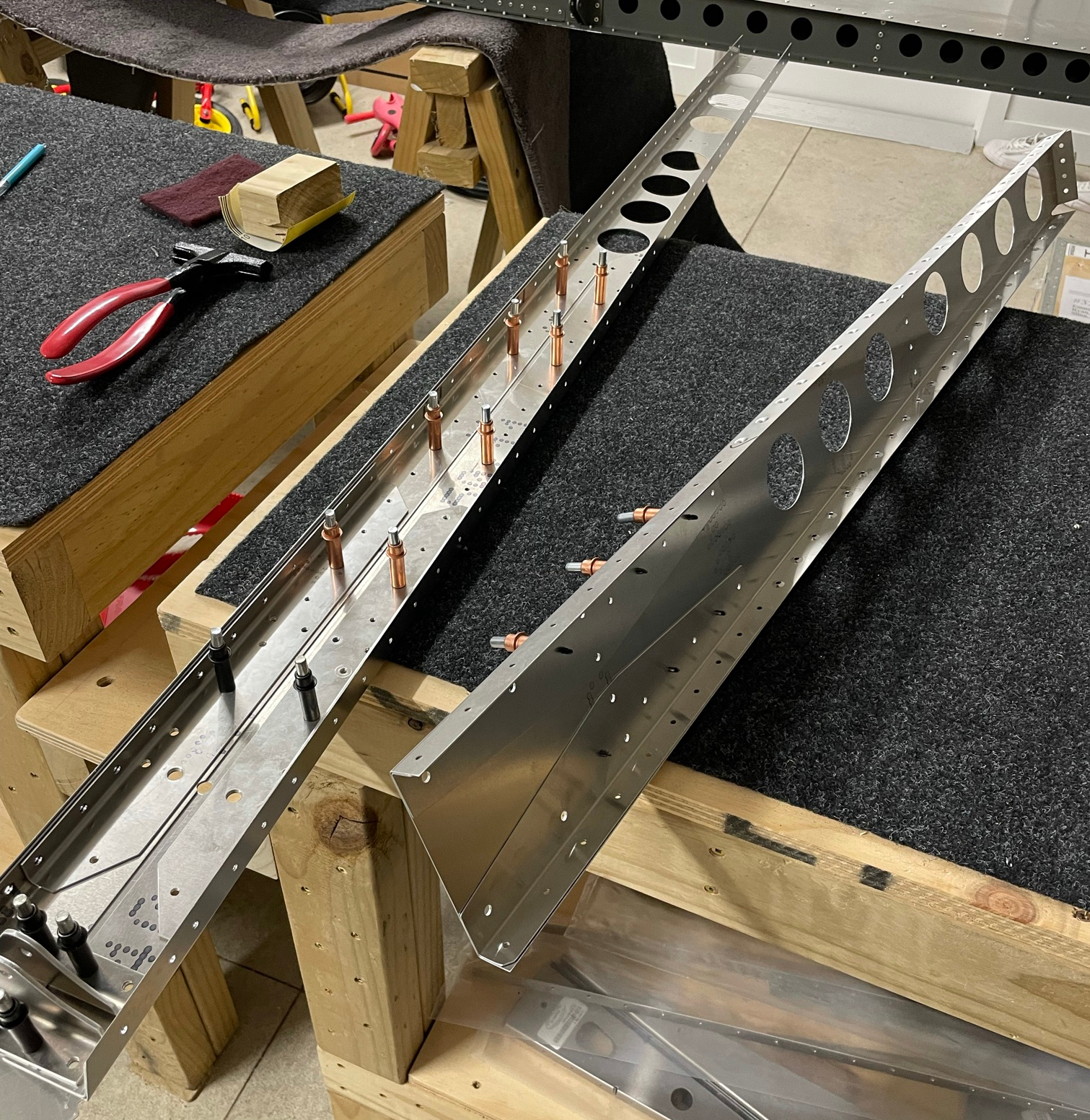
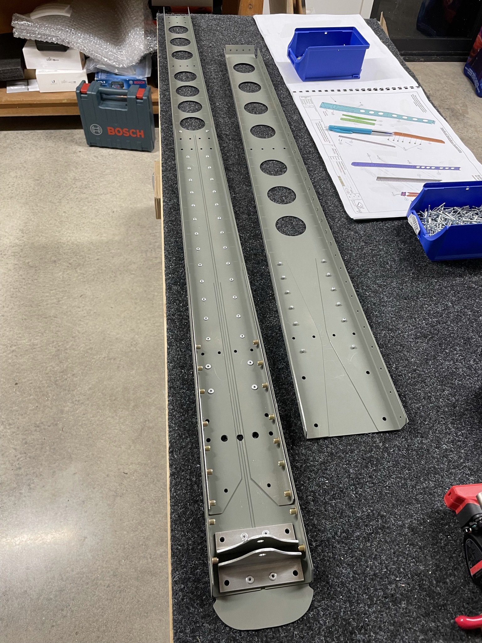
A quick test fit shows good alignment of the parts.
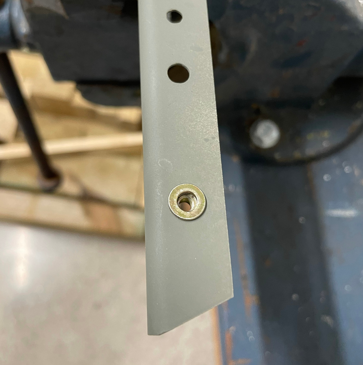
Rivnuts
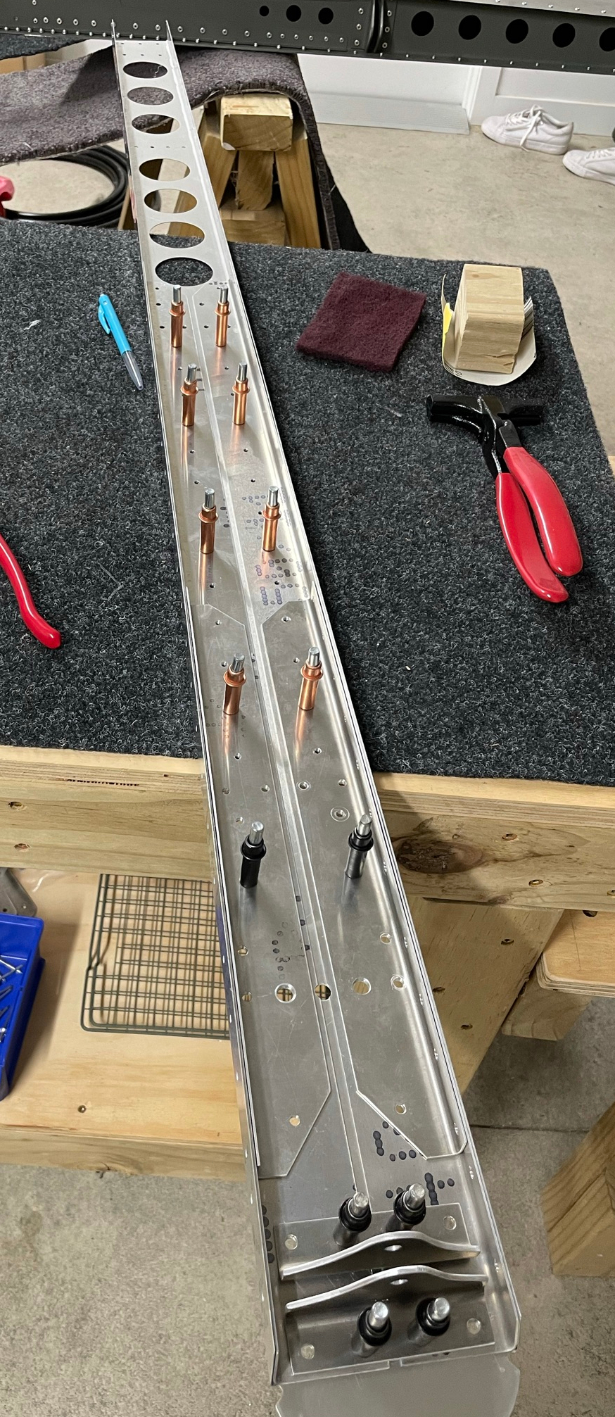
There are a number of rivnuts that need to be fitted to the rear spar doubler plates to facilitate eventual attachment to the fuselage.
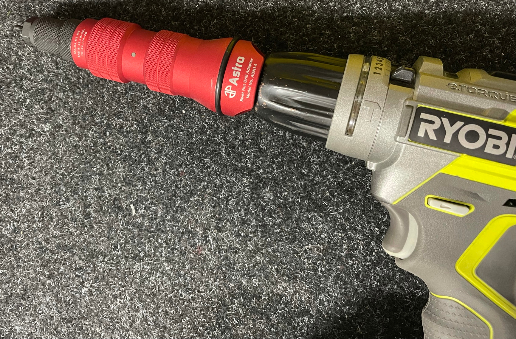
I've gone with the Astro drill adaptor rather than a hand puller, mainly because I love toys, and it seemed a slicker option.
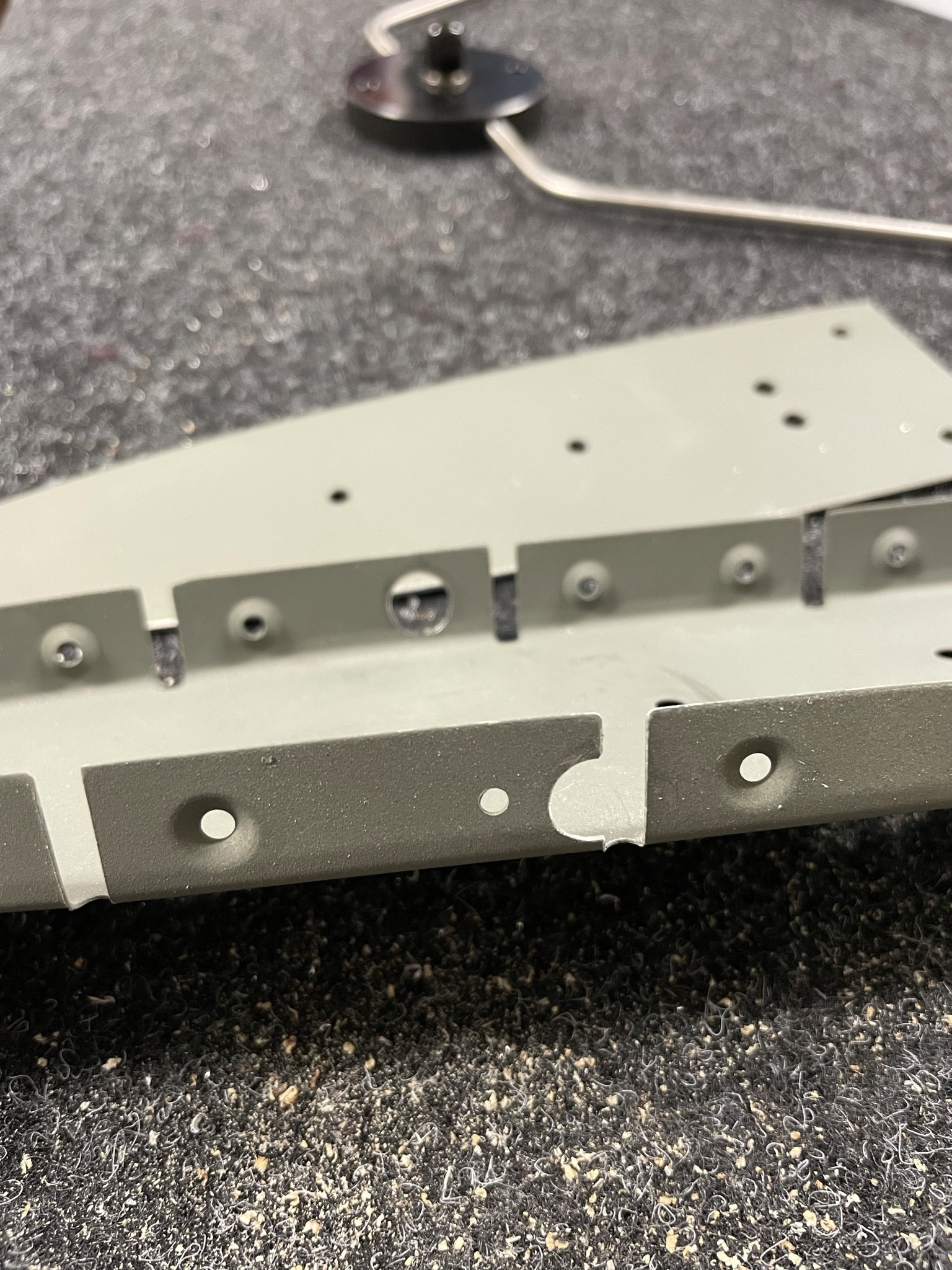
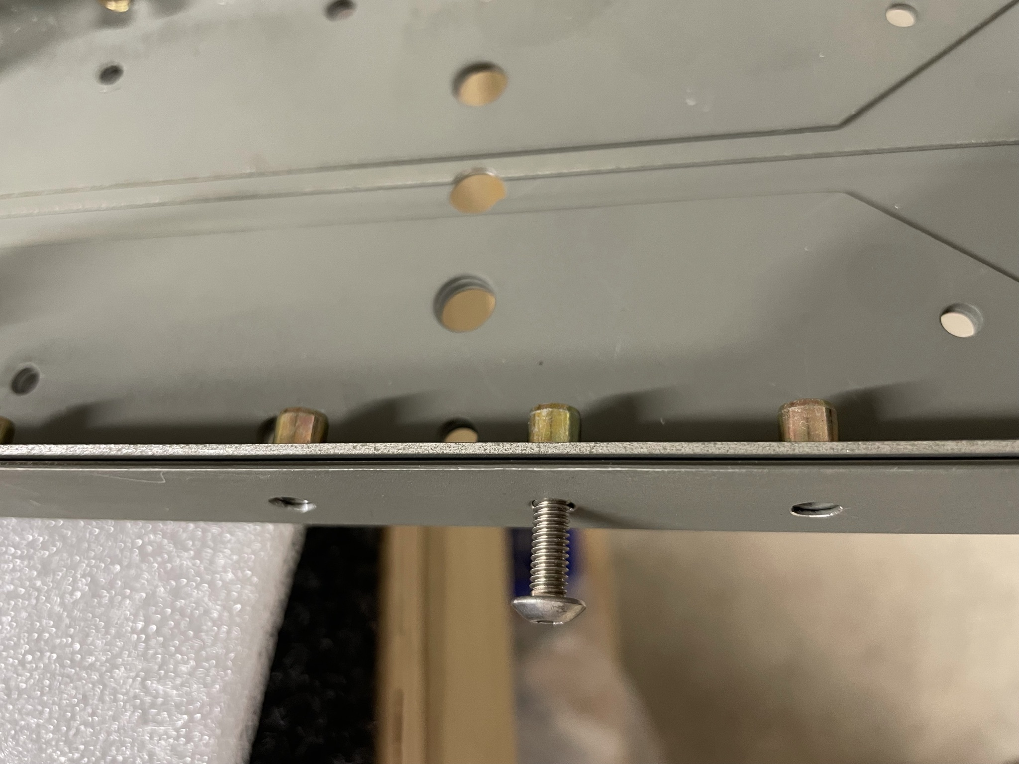
These are fitted to the two inner spar doublers on each side, and then the spar needs to have the matching holes updrilled to 4.5mm so that the M4 bolts can pass through into the rivnuts. You would be pretty dark after riveting if you forgot this, and although the manual doesn't call it out, Evan's video makes it quite clear.
Other builders have also enlarged the lower two spar holes on each side to 9.5mm so that the rivnut flanges fit through flush, which I've done as well.
The rivnut holes need to be themselves upsized to 5.8mm to fit the nut OD. The best way seems to be to drill to 5.5mm using a drill bit, then slowly increase the diameter with a hand reamer to ensure the tightest possible fit, and a nice circular hole.
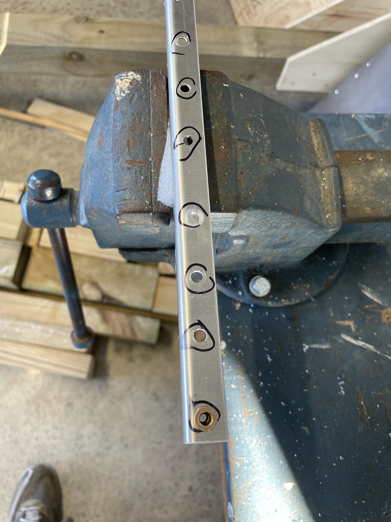
With all the holes reamed it's time to prime!
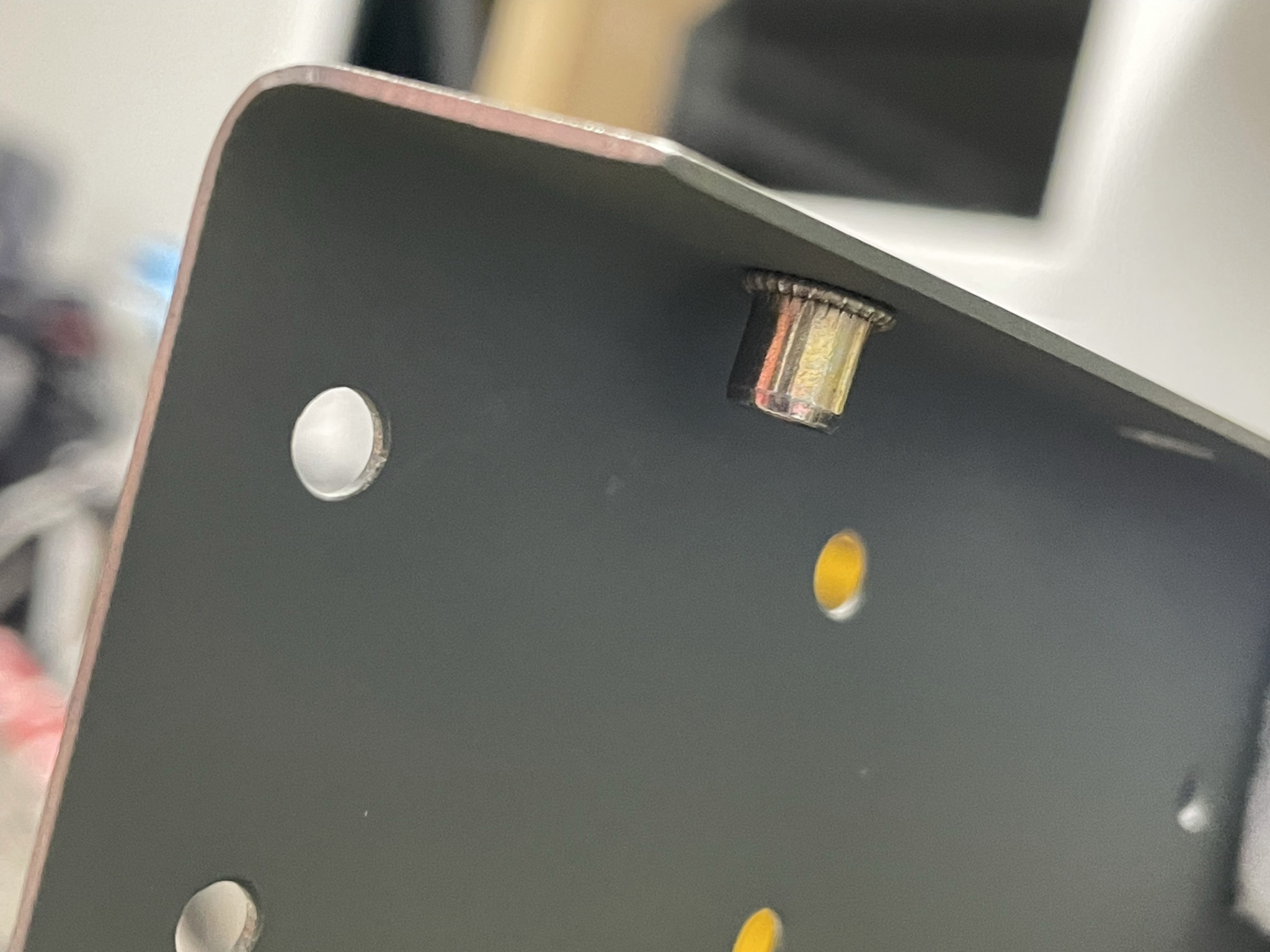
The rivnut puller has a bit of a trick to it to get the mandrel out after pulling, but makes short work of the installation once you get the hang of it.
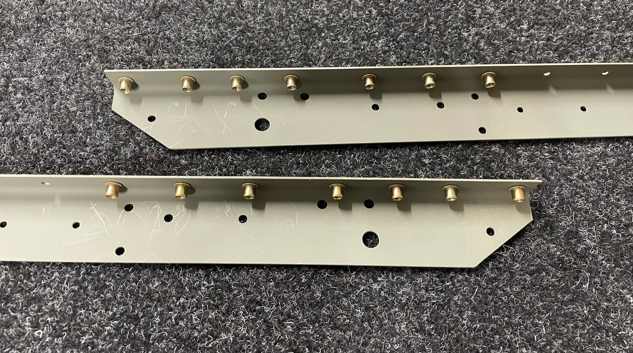
VS Spar Assembly
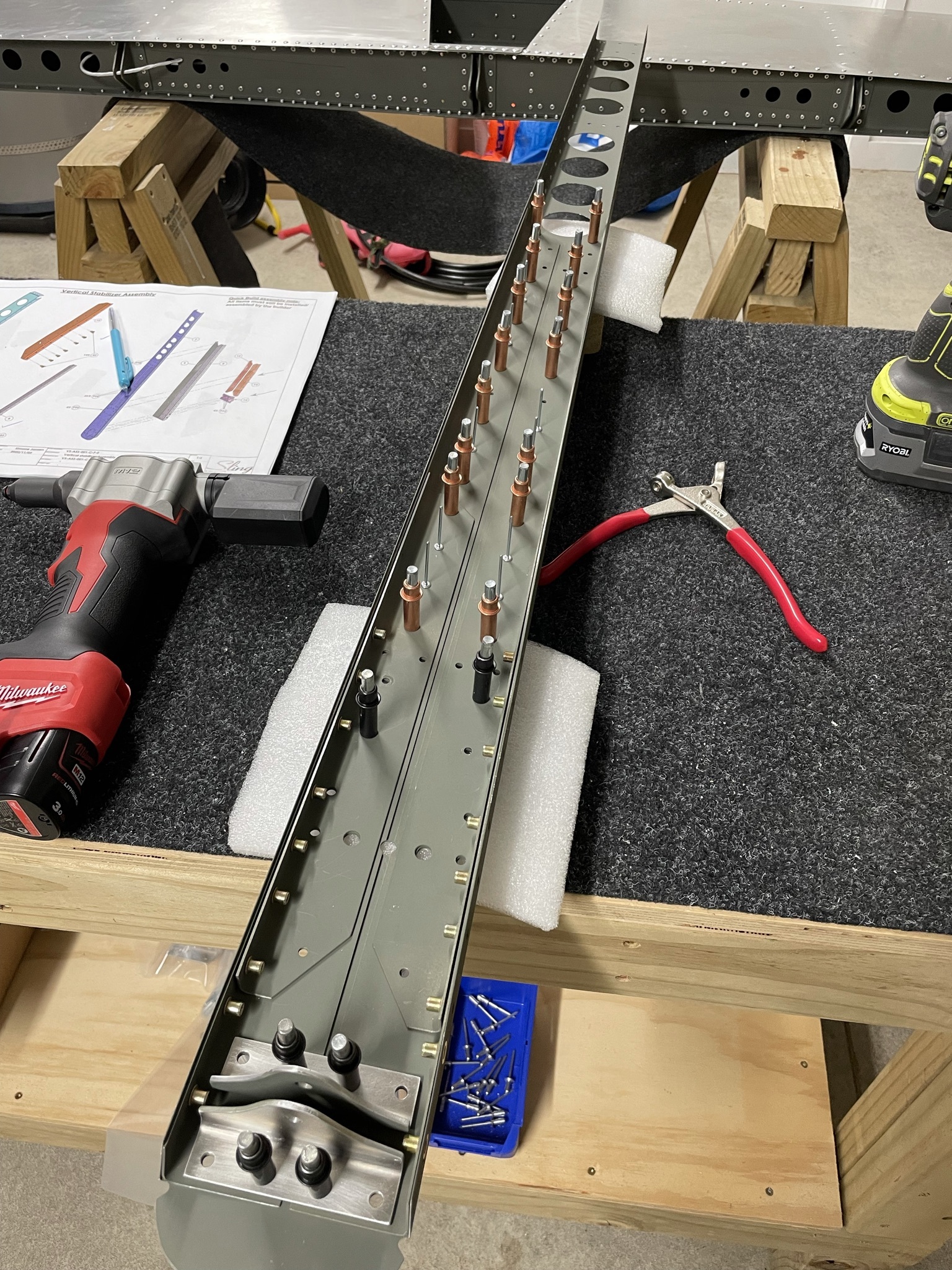
With the prep done and rivnuts in, there's not much trouble getting the spars assembled and riveted. The only thing to note is that the rivets go in opposite directions on the front and rear spars so the shop heads are on the inside.
VS structure test assembly
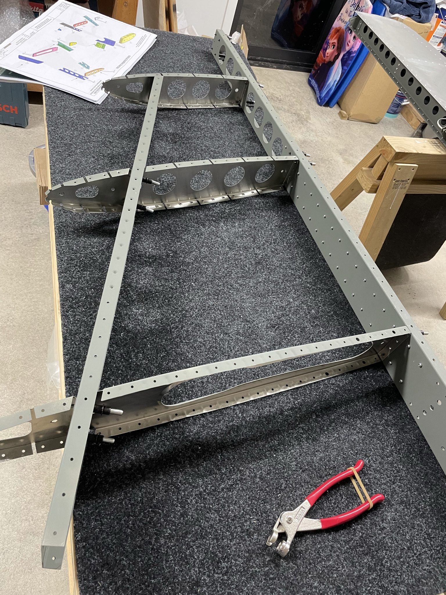
Initial assembly of the VS structure is straightforward, only three internal ribs and front ribs. This can be riveted straight away but I might disassemble it to drill/enlarge holes for the coaxial VOR antenna cable and tail strobe lighting wire so will leave it clecoed for now.
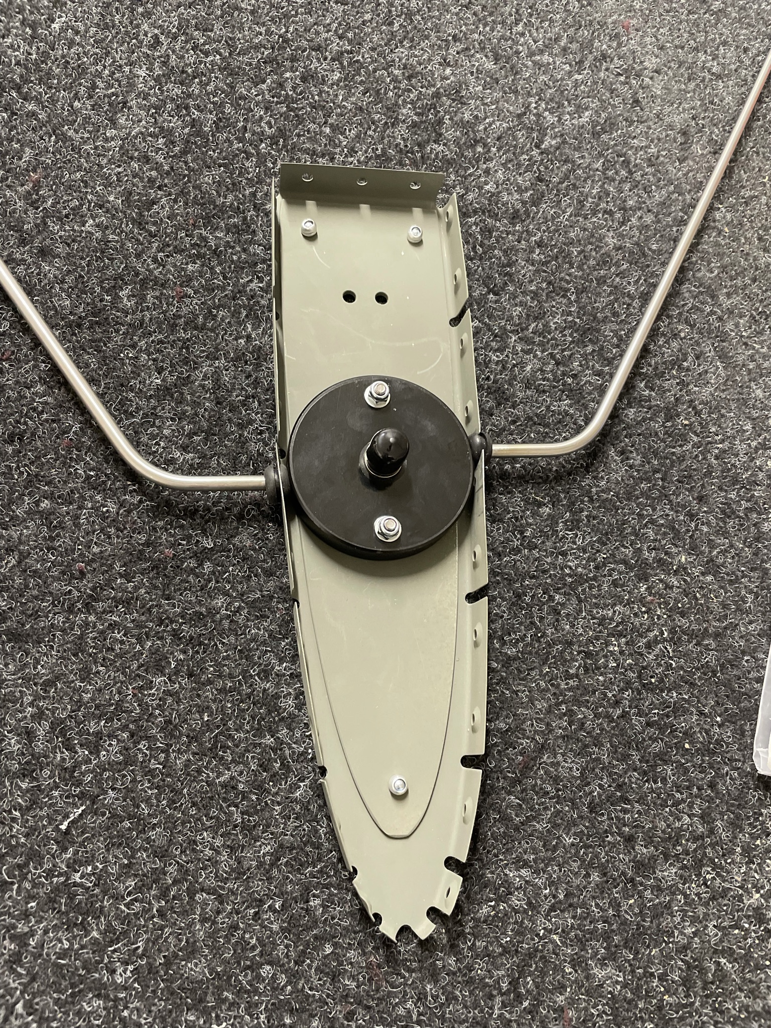
VOR antenna mounting
The VOR antenna I've gone with is the RAMI AV-525, which is a bent-dipole antenna with an internal balun. As the antenna is a dipole, the signal is unbalanced, which requires a balun. The otherwise-identical AV-12 needs one built out of coax, but the AV-525 has this built in and just needs a BNC plug on the end of your cable, so the choice is very easy.
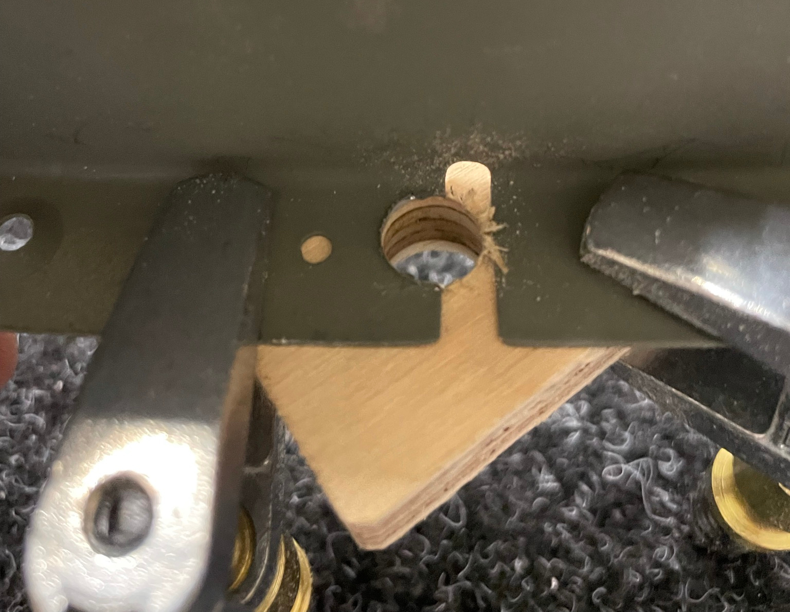
This is mounted into the top rib with a doubler plate, and requires one rivet hole to be drilled up to 9.5mm, and a 9.5mm diameter semicircular cut made in the opposite rib. The antenna elements are offset so these don't line up.
I'd been putting this off due to the challenge of drilling a half-circle in the flange of the rib, but had the (potentially) bright idea of clamping a plywood offcut onto the flange and using that as a drill guide for my step drill. Pleasingly, this worked a treat.