Rudder Assembly
And a workshop upgrade...
Table legs
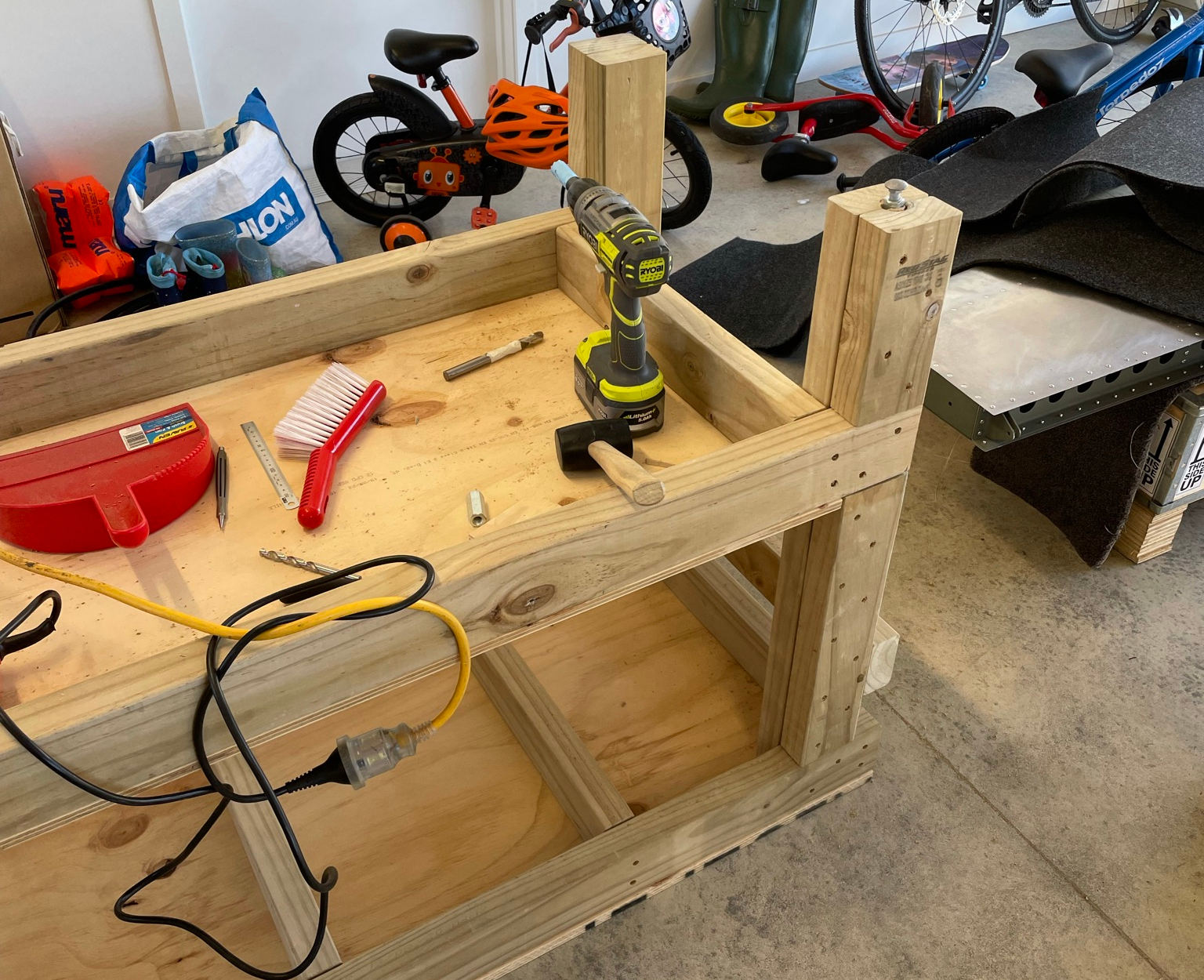
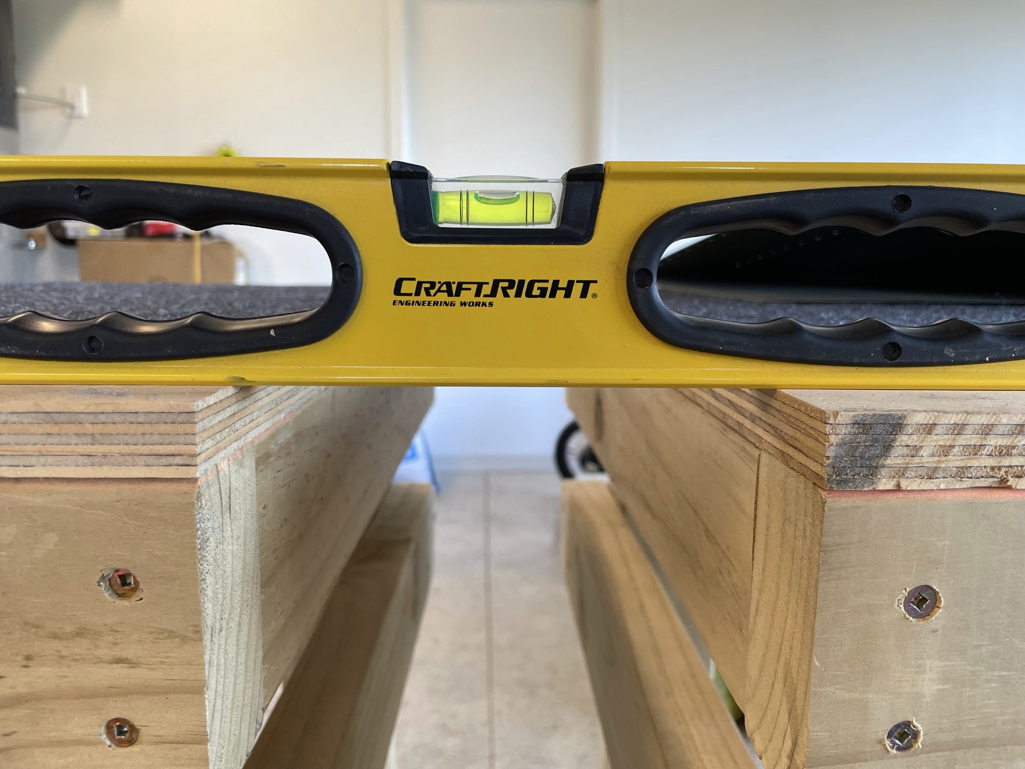
Despite my best efforts, one of my EAA-1000 tables has a slight wobble, and the tables are not quite the same height. This was a bit annoying while assembling the horizontal stabiliser, and I wanted to rectify this before getting to the elevator.
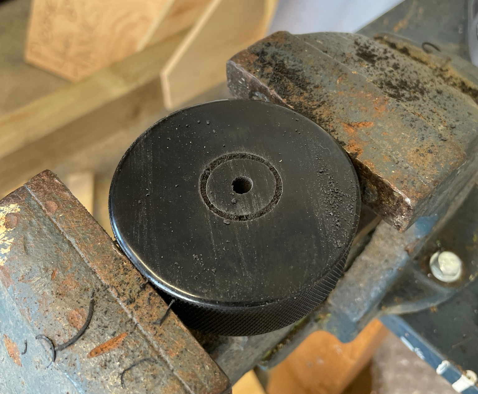
An RV-14 builder who I also stole the DRDT-2 mounting platform idea from has linked a nice way to add leveler feet to a wooden table by setting it on top of hockey pucks, drilled out to receive the head of a coach bolt, itself inserted into a connector nut hammered into the leg.
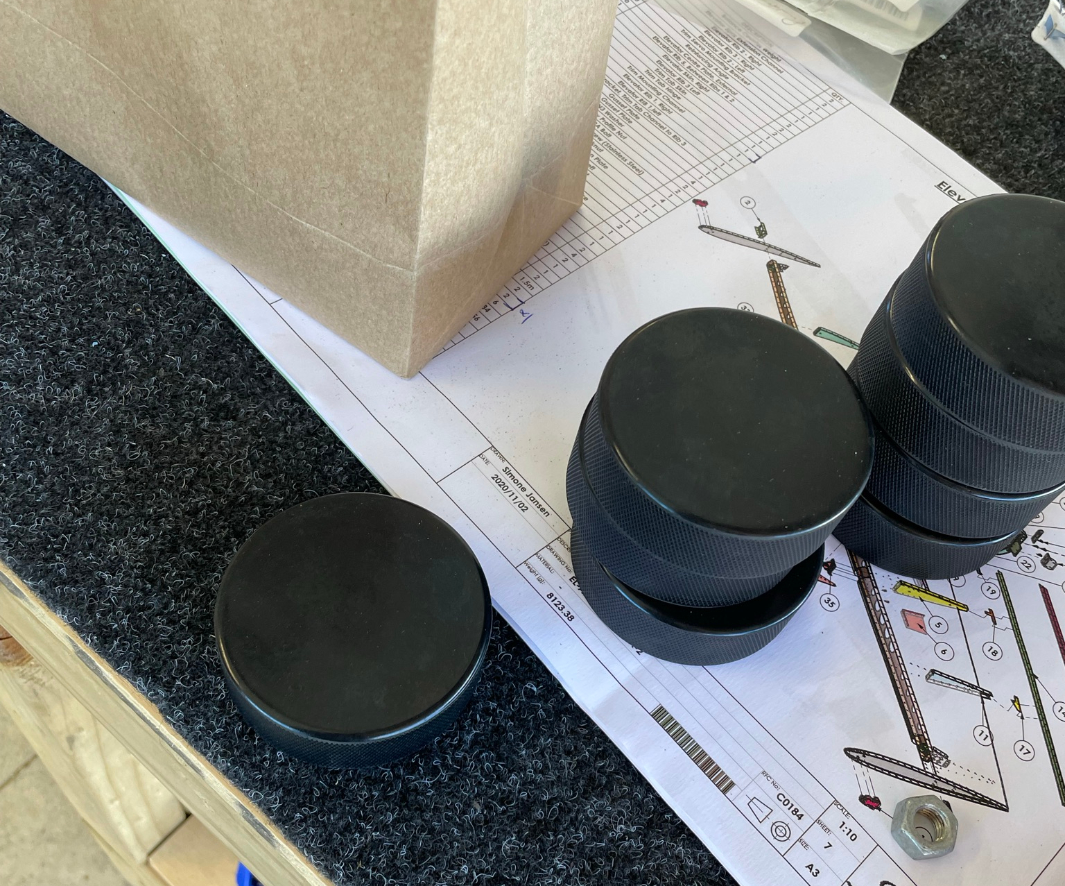
After using a combination of a hole saw and 15mm drill bit to create a hole (slightly undersize), I hammered in the M8 connector nut using a rubber mallet, and inserted the coach bolts.
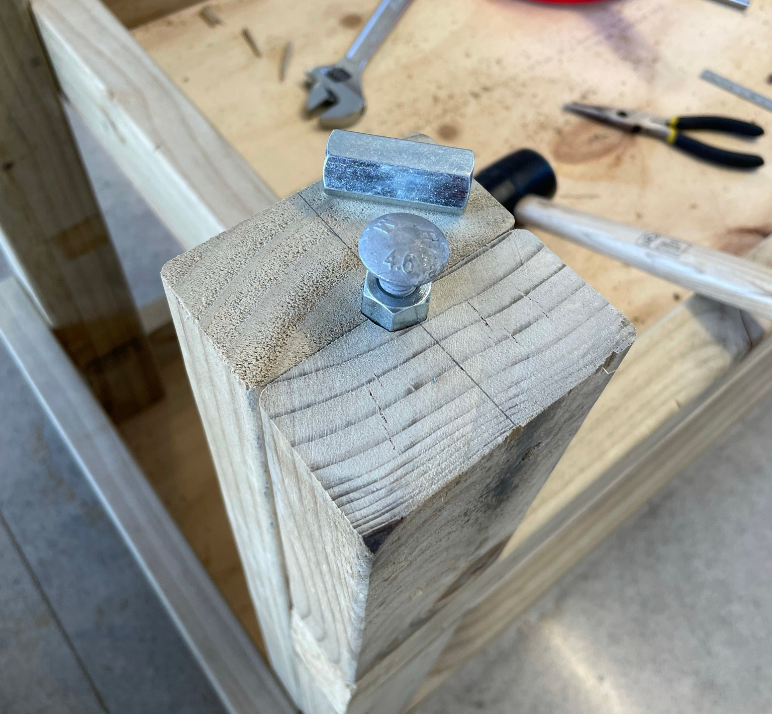
A larger hole saw and and Stanley knife make short work of the depression for the puck.
Once the tables are flipped back and resting on the pucks, the bolt is easily turned by an open crescent wrench to individually adjust the leg lengths.
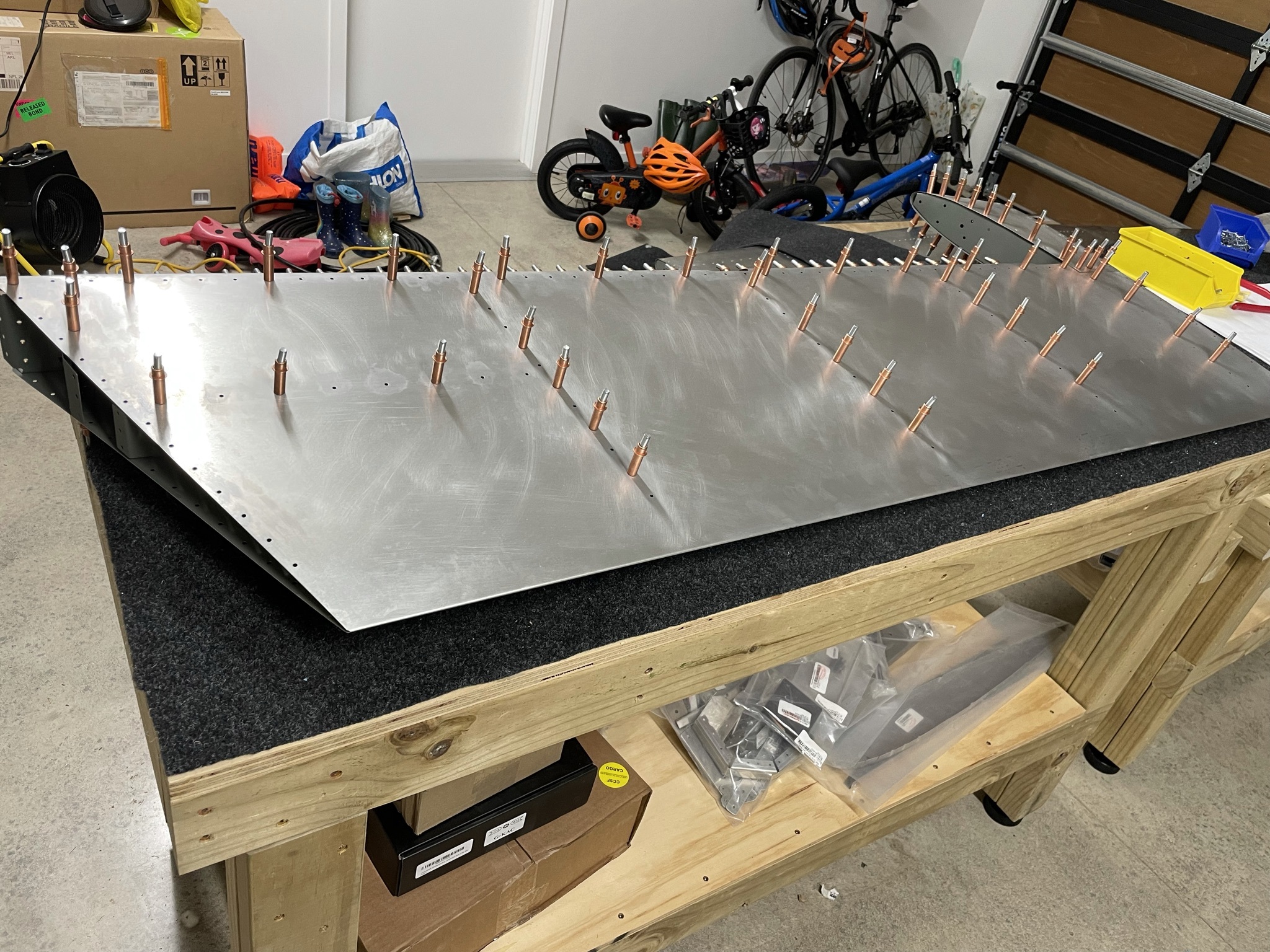
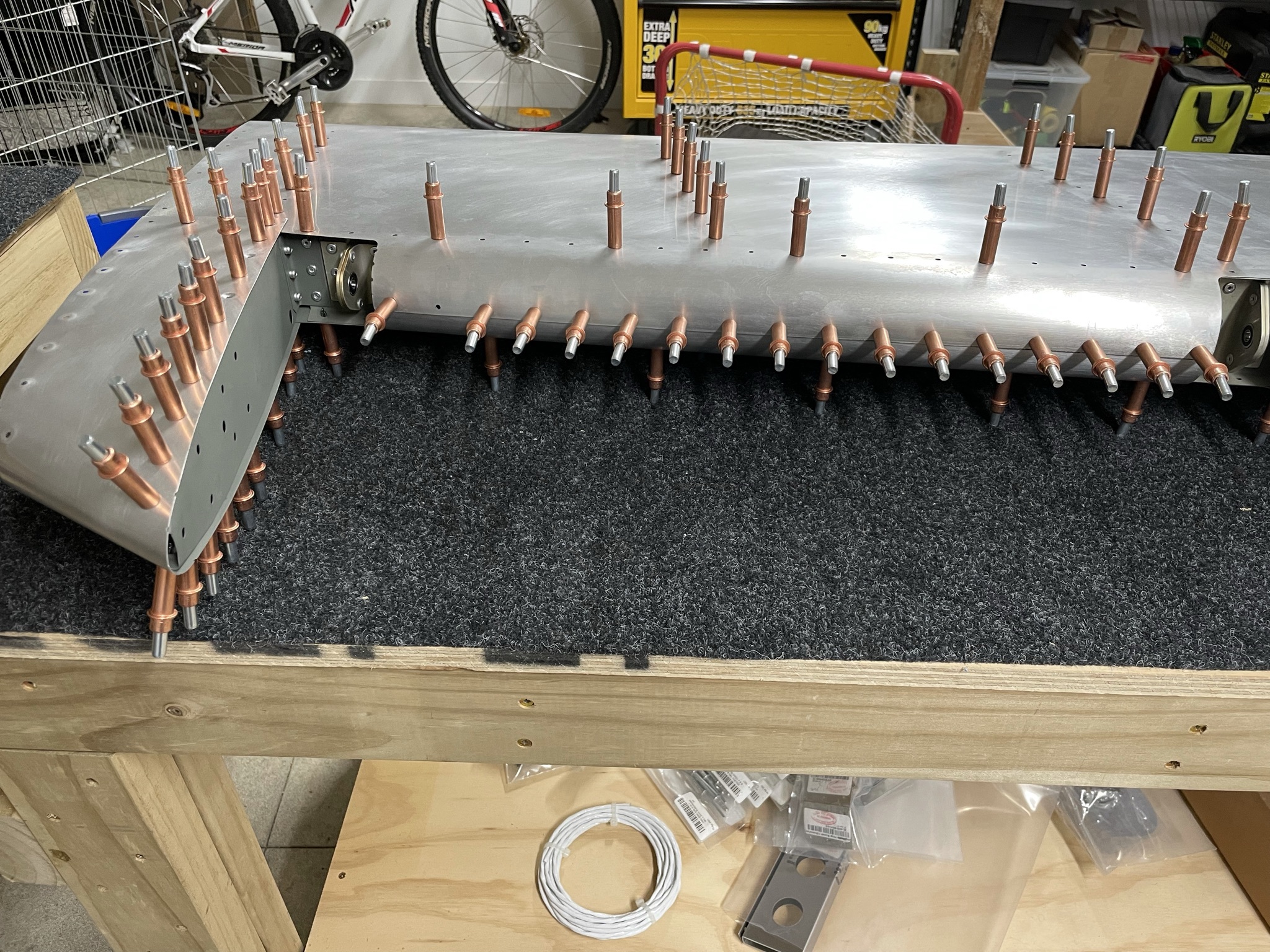
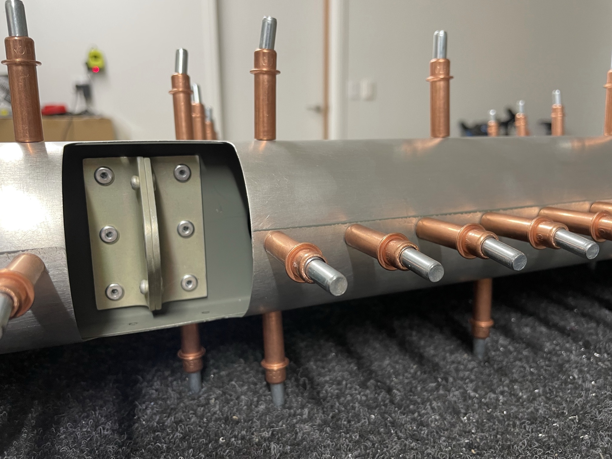
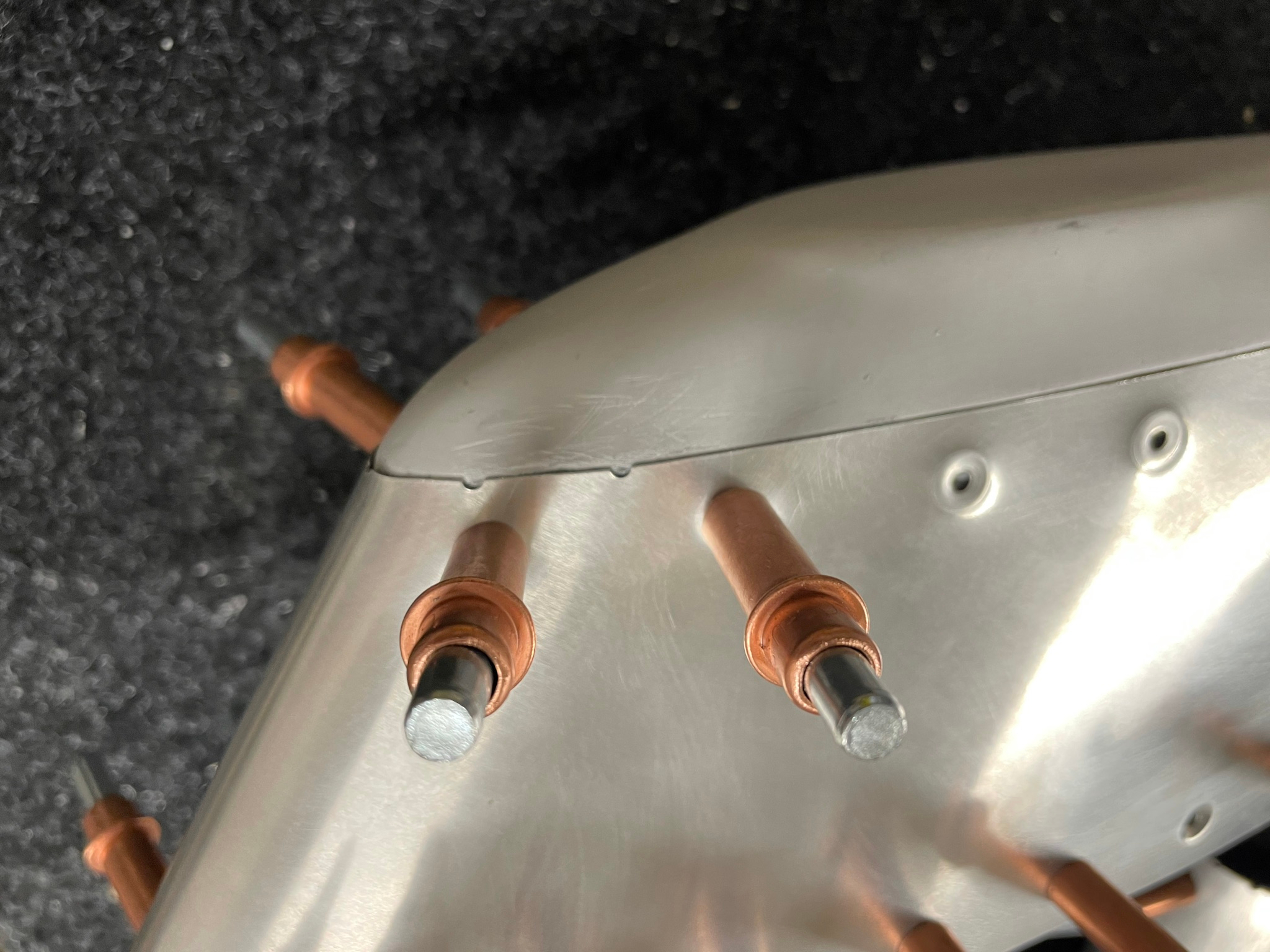
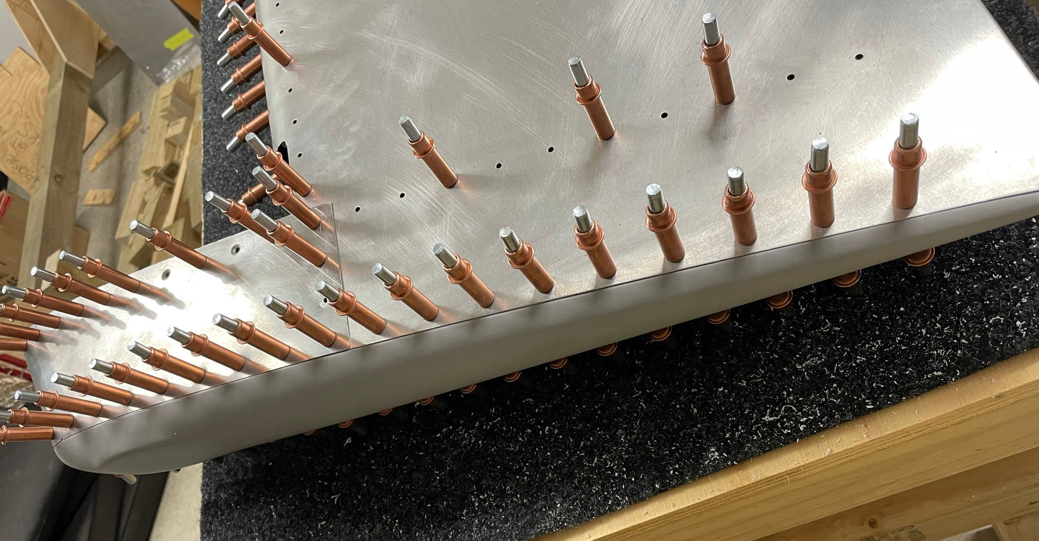
Rudder skin
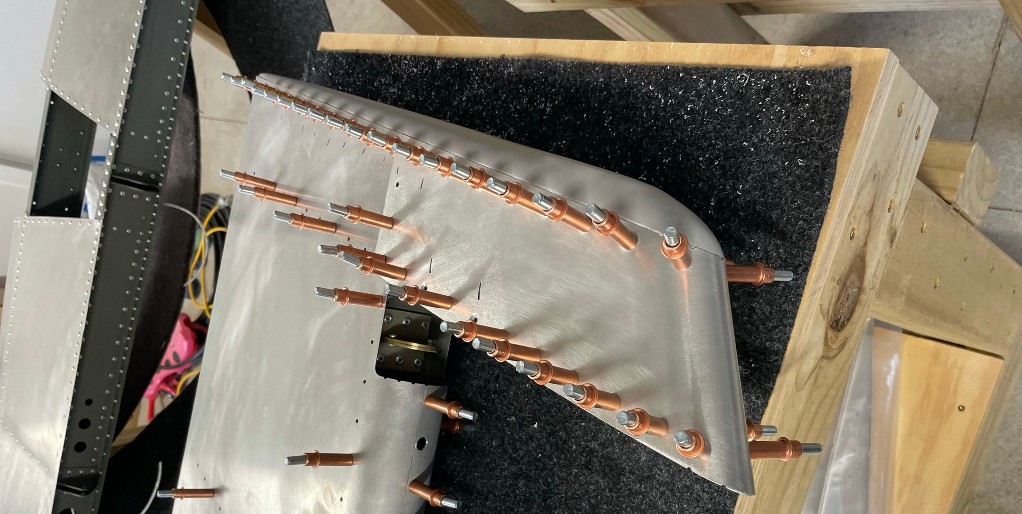
Now that my tables are a joy to work on, riveting the rudder structure was straightforward, and the skin goes on easily.
Rudder systems
Tail beacon wiring
The rudder requires a wire run for the beacon light, which is mounted on the tip. The standard factory hole for this in in the top rib implies it should run in front of the rudder spar, however this seems like it will have the potential to interfere with the top hinge, so I'm going to drill another hole in the top rib behind the spar and pass it through the adjacent lightening hole and behind the spar.
Static wicks
Because I'm planning on adding both static wicks and a bonding strap, I also need to find locations for these. I'm awaiting nut plates, copper braid and the associated hardware for this from Aircraft Spruce. I've detailed my sources for this and the required hardware on my Resources page.
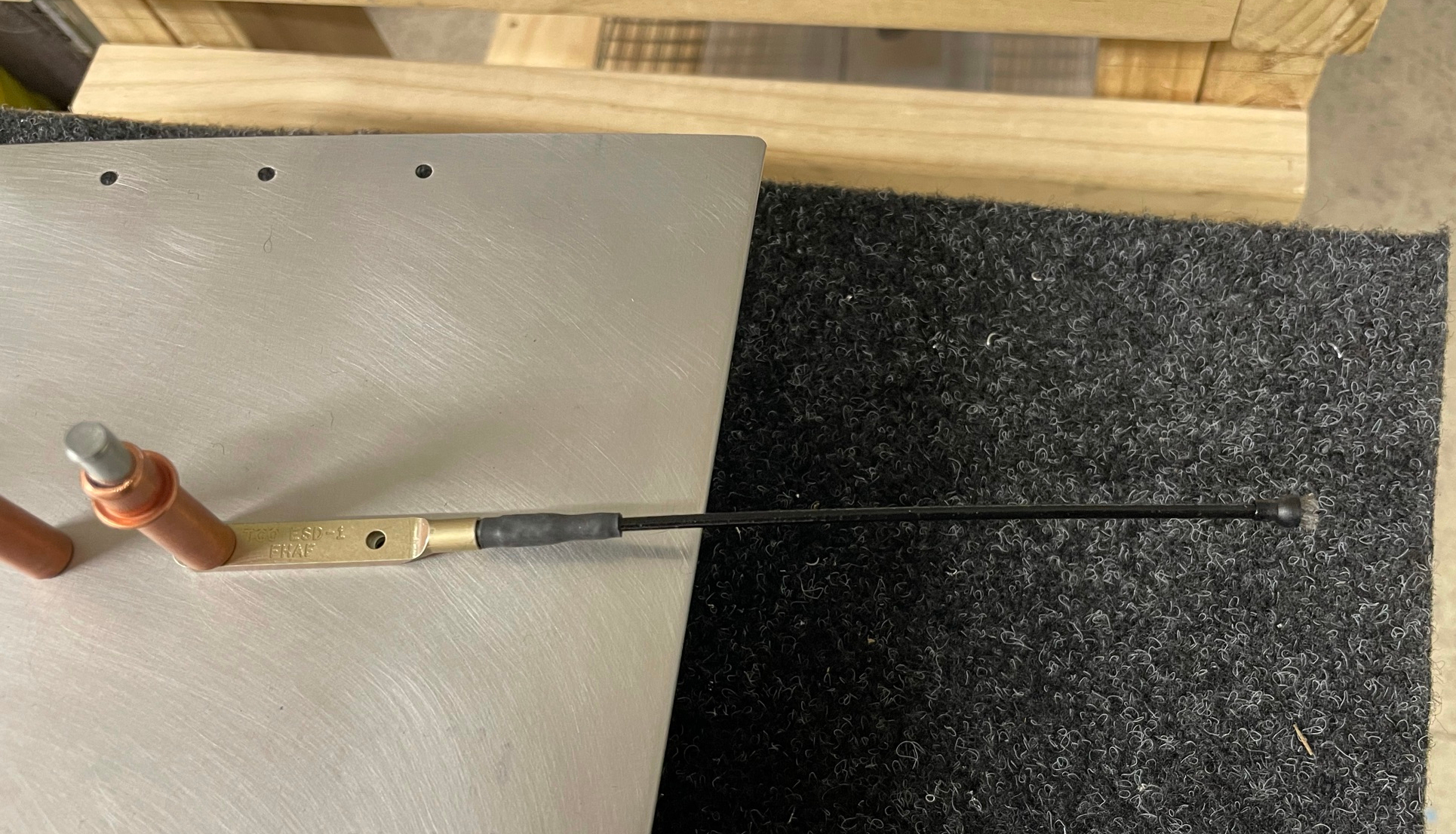
The final two rivet holes on the trailing edge are close enough to the wick hole spacing that they should be able to be enlarged for the nutplates to go under.
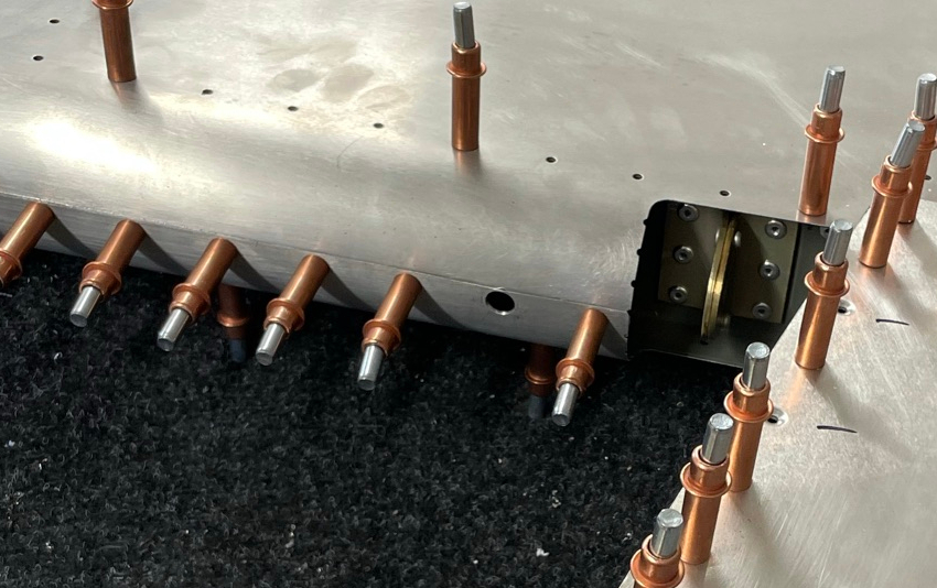
The middle hinge bracket opening has a little extra space in the skin opening below, which looks to be a good place to mount the nut plate for the bonding strap. I'll drill out the second rivet hole down (as for the beacon wire) to pass the strap through to mate to the VS nut plate, which I will add to the rear VS spar.
Rudder tip fitting
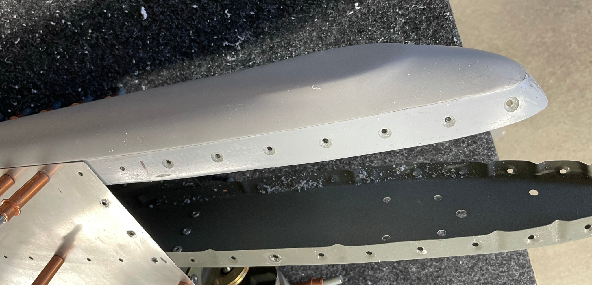
The fibreglass rudder tip has to be match drilled using the tip skin as a guide, then the front 7 holes require countersinking to match the dimpled skin.
This is easier than I had feared, although it's good to have someone to help hold the tip in position until at least the first couple of holes are in and secured with clecos. My tip seemed to have a little extra material right at the front, but I was able to achieve a good fit after sanding down the joggle slightly.
After that the tip skin is removed, (re)dimpled and the tip can be countersunk to match. I'm going to add AN960PD-4 aluminium washers as has been suggested by Evan and have ordered these.